Home/
Registry/
Suzuki/
Samurai/
1986-1995/
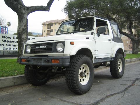
“the Go-Cart”/
Photo
supermotors.net/registry/media/985232
Suzuki Sidekick/Geo Tracker 8v EFI Swap into Samurai - ECM C1 Pinout & Wiring

Reference · 1986-1995 SamuraiAll 73 wiring diagrams
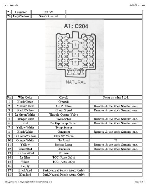
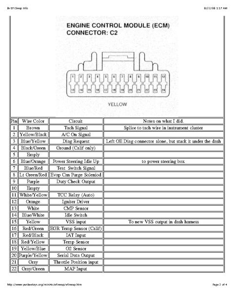
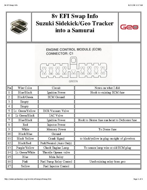
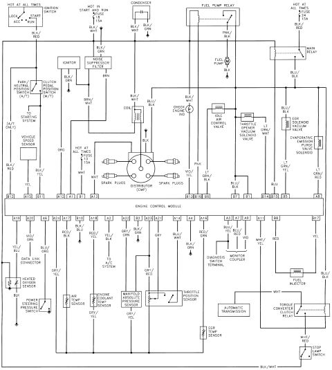


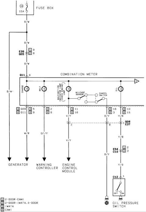
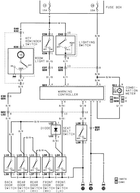

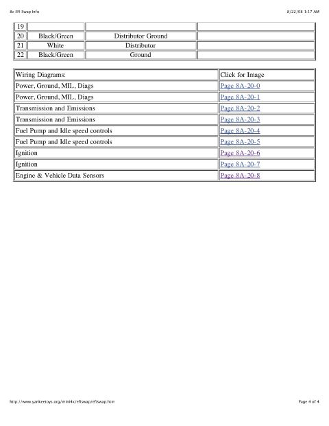

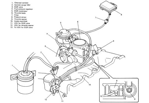

8v EFI swap pinout: Suzuki Sidekick/Geo Tracker ECM connector C1 (green) with pin, wire color, circuit and swap notes for installing into a Samurai (ignition power, IAC, injector, fuel pump relay, etc.).
Part of 1986-1995 Suzuki Samurai Wiring Diagrams
This document is page 1 of 4 of an "8v EFI Swap Info" guide describing how to swap a Suzuki Sidekick/Geo Tracker 8-valve EFI system into a Suzuki Samurai. It focuses on the Engine Control Module (ECM) Connector C1 (the green connector), showing a pinout diagram with 17 pin positions and a detailed table listing each pin's wire color, circuit function, and the author's installation notes. Key circuits documented include Ignition Power (pins 1 and 7, Blue/Black), ECM Ground (pin 2, Black/Green), EGR Vacuum Valve (pin 5), IAC Valve (pin 6), Injector Power (pin 8, Red), Memory Power (pin 9, White, connected to the Dome fuse), Ground (pin 10), Crank Signal (pin 11, Black/Yellow), Park/Neutral for automatics (pin 12), Check Engine Lamp (pin 13, Purple/Yellow), Throttle Opener Valve (pin 14), Main Relay (pin 15, Blue), Fuel Pump Relay Control (pin 16, Pink, using the existing Geo relay), and Fuel Injector Control (pin 17, Yellow). Pins 3 and 4 are empty. The notes column explains where the author connected each wire in the Samurai, such as tapping the existing ECM fuse, Heater/Defroster fuses, and the wire in the plug right of the glovebox. Source URL: yankeetoys.org.
Is this accurate? Sign in to help verify it.
Frequently asked questions
- What is the wire color and function of pin 1 on the ECM C1 connector?
- Pin 1 is Blue/Black, Ignition Power. The author's note says to hook it to the existing ECM fuse.
- Which pin controls the fuel pump relay in the 8v EFI swap?
- Pin 16, a Pink wire, is the Fuel Pump Relay Control. The author used the existing relay from the Geo.
- Which pins on ECM connector C1 are empty?
- Pins 3 and 4 are listed as Empty.
- Where does the Memory Power wire (pin 9) connect in the swap?
- Pin 9 is a White wire for Memory Power, and the notes say it goes to the Dome fuse.
- What color is the ECM C1 connector?
- The document labels the C1 connector as GREEN.

No comments yet.