Home/
Registry/
Suzuki/
Samurai/
1986-1995/
“the Go-Cart”/
Photo
supermotors.net/registry/media/985233
Suzuki Samurai 8v EFI Swap ECM Connector C2 Pinout - Wire Colors & Circuits
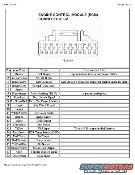
Engine Control Module connector C2 pinout chart listing pin numbers, wire colors and circuit functions.
This document is page 2 of 4 from an '8v EFI Swap Info' guide printed from yankeetoys.org (dated 8/22/08). It documents the Engine Control Module (ECM) connector C2, a yellow 24-pin connector shown in a diagram with pins numbered 1-12 on the top row and 13-24 on the bottom row. A table lists pins 1 through 22 with their wire colors, circuit functions, and swap installation notes. Circuits covered include the Tach Signal (Brown, pin 1), A/C On Signal, Diagnostic Request, California-only Ground, Power Steering Idle Up, Test Switch Signal, Evaporative Canister Purge Solenoid, Duty Check Output, TCC Relay (automatic transmission), Igniter Driver, CMP Sensor, Idle Switch, VSS input, EGR Temp Sensor (California), IAT Input, Temp Sensor, O2 Sensor, Serial Data Output, Throttle Position input, and MAP Input. Pins 5 and 10 are empty. The author's notes indicate splicing the tach signal to the instrument cluster tach wire, leaving the OE diagnostic connector intact but relocating it under the dash, routing the power steering idle-up circuit to the power steering box, and connecting the VSS input to a new VSS output in the dash harness. This is useful for anyone wiring an 8-valve EFI engine swap into a Suzuki Samurai.
Is this accurate? Sign in to help verify it.
Frequently asked questions
- What color is the ECM C2 connector and how many pins does it have?
- The ECM connector C2 is yellow and has 24 pin positions, numbered 1-12 on the top row and 13-24 on the bottom row.
- Which pin on the C2 connector is the tach signal and what wire color is it?
- Pin 1 is the Tach Signal on a Brown wire. The author's note says to splice it to the tach wire in the instrument cluster.
- Which pins on the ECM C2 connector are empty?
- Pins 5 and 10 are listed as empty.
- What wire color is the O2 sensor input on the C2 connector?
- The O2 Sensor is on pin 19, wire color Yellow/Blue.
- Which circuits are marked as California-only?
- Pin 4, Black/Green Ground (Calif only), and pin 16, Red/Green EGR Temp Sensor (Calif).
Comments
More from this build





No comments yet.