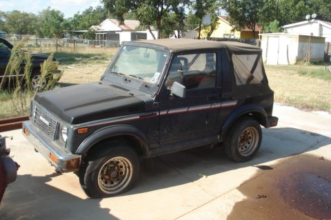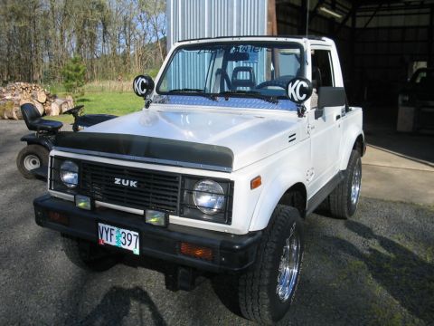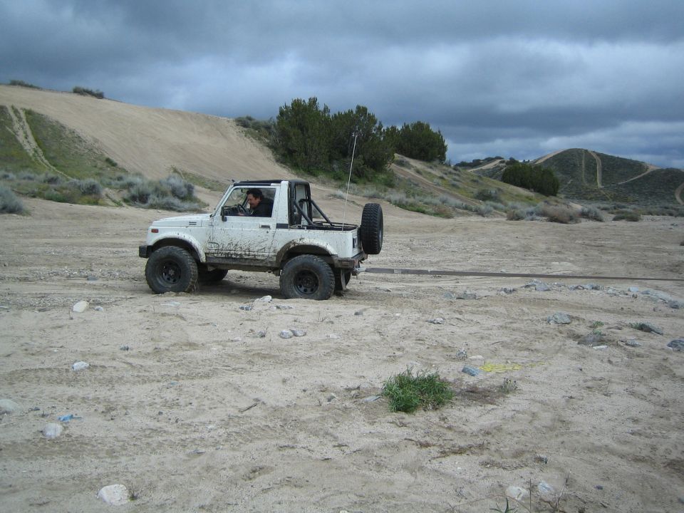
The Suzuki Samurai (1986-1995) is the American-market version of the SJ413, a body-on-frame 4x4 of about 2,100 pounds with leaf springs and solid axles at both ends. Two closely related engines cover the run: a carbureted 1,324 cc G13A rated at about 63 hp through 1989, then a throttle-body injected 1,298 cc G13BA at 66 hp from 1990. Every US Samurai used a five-speed manual, and all but a short-lived 1991-1993 two-wheel-drive version paired it with part-time 4WD and a two-speed transfer case. It arrived in late 1985, sold in huge numbers early on, weathered the 1988 Consumer Reports rollover controversy, and left the US market after 1995.
Platform
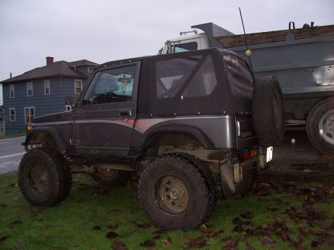
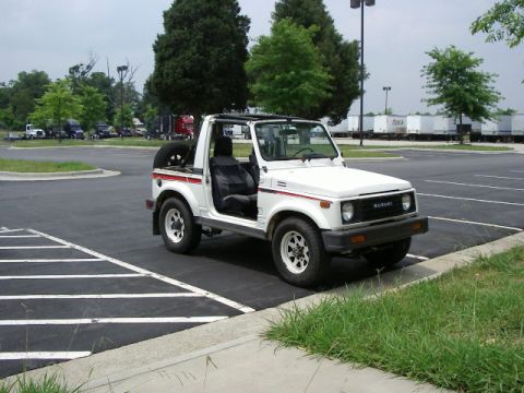
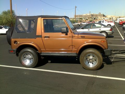
The 1986-1995 Suzuki Samurai is the US name for the SJ413, a steel body bolted to a ladder frame on a 79.9 inch wheelbase. Curb weight runs about 2,050 to 2,100 pounds depending on body style and year, and that low weight is the number that matters most on this truck. Both axles are solid and hang on leaf springs, front and rear. Two body styles came here: the soft-top convertible and the steel hardtop (tin top), the hardtop being the rarer of the two in most of the country. Ground clearance, short overhangs, and low weight made it a capable trail rig straight off the lot despite modest power.
Engine
Two closely related fours cover the run, both from Suzuki's G family: SOHC, 8 valves, aluminum block and head, non-interference valvetrain.
- 1986-1989: carbureted G13A, 1,324 cc, rated at about 63 hp and roughly 74 lb-ft of torque. The feedback carburetor and its vacuum plumbing are the usual source of driveability complaints on surviving examples.
- 1990-1995: G13BA, 1,298 cc, with throttle-body fuel injection, rated at 66 hp and about 76 lb-ft. Displacement actually shrank a little, but the injected engine makes more power, starts easier, and idles cleaner, and the injection compensates at altitude where the carb does not.
All ratings are SAE net. Nobody bought a Samurai for the horsepower; the gearing does the work.
Drivetrain and transmission
Every US Samurai used a five-speed manual; no automatic was ever offered here. Nearly all are part-time 4WD with manual locking front hubs and a gear-driven two-speed transfer case (1.409:1 high range, 2.268:1 low range). The transfer case is the platform's best feature. It is a separate unit connected to the transmission by a short intermediate driveshaft, which is exactly why the aftermarket can swap in deep reduction gearsets so easily. Axles are Suzuki's own small solid units front and rear, light and simple, with the front using a conventional kingpin-style knuckle. The front differential changed from a 4-pinion to a 2-pinion carrier in 1990, which affects locker fitment, so check the year before ordering traction parts. Suzuki also sold a two-wheel-drive Samurai in small numbers from 1991 to 1993; it kept the five-speed but has no transfer case or driven front axle.
Year-by-year changes
- 1986: US launch (sales began in late 1985). Carbureted, JA and JX trims, roughly 47,000 sold in the first year.
- 1988.5: mid-year running update. Softer springs and shocks, a larger front anti-sway bar, a revised dash with square vents, and a shorter 0.865:1 fifth gear replacing the 0.795:1 to help it hold highway speed. These are commonly called 1988.5 trucks and are visibly different inside from early cars.
- 1990: the throttle-body injected 1,298 cc G13BA replaces the carbureted G13A, 66 hp. The JL trim arrives, and the front differential switches to a 2-pinion carrier.
- 1991: two-wheel-drive JA and JS models added.
- 1994: two-wheel-drive models dropped; the 4WD JL carries on.
- 1995: final US model year. Late trucks sold in small numbers as the Sidekick and Geo Tracker had taken over the showroom.
Trims
Trim content stayed simple. Through 1990 the base JA was a stripped tub, vinyl seats, minimal trim, and the JX added the common convenience items (better seats and trim, rear seat, tachometer on many examples). The JL arrived for 1990 as the better-equipped 4WD model and was the only trim left by 1994. The 1991-1993 two-wheel-drive line reused the JA name for a bare-bones truck with no top or rear seat, alongside a JS with a soft top and rear seat that lasted only briefly. Trim availability shifted year to year and regional dealer packages muddy the picture, so verify equipment on the individual truck rather than trusting the badge.
The 1988 Consumer Reports episode
In June 1988 Consumer Reports rated the Samurai "Not Acceptable" after it tipped onto its outriggers in the magazine's short-course avoidance maneuver, and US sales fell hard afterward. Suzuki disputed the testing methods and sued Consumers Union for defamation in 1996; the case settled in 2004 with no money changing hands and a clarifying statement from Consumers Union that it never intended to state the Samurai easily rolls over in routine driving. Whatever side of that fight you land on, the tall, narrow, short-wheelbase geometry rewards the same driving habits as any early CJ or first-generation 4x4.
Why crawlers love it
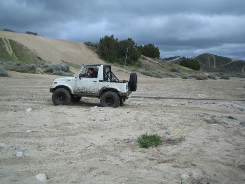
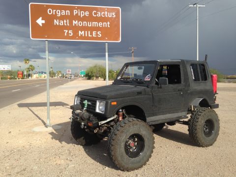
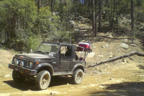
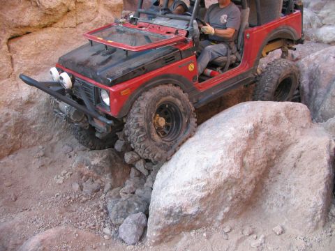
The Samurai turned into a rock-crawling staple for plain mechanical reasons: about 2,100 pounds of curb weight, solid axles at both ends, leaf springs that are trivial to lift or swap, and a 2.268:1 low-range transfer case that accepts aftermarket reduction gears. A locked, geared Samurai on 31s or 33s will follow full-size rigs through trails that would hang up trucks twice its weight, and broken parts are cheap and light enough to carry as spares.
Asked all the time
What engine does the 1986-1995 Suzuki Samurai have?
The US Suzuki Samurai used two closely related SOHC 8-valve fours from Suzuki's G family, both with aluminum block and head. From 1986 to 1989 it was the carbureted 1,324 cc G13A, rated at about 63 hp. For 1990 Suzuki switched to the 1,298 cc G13BA with throttle-body fuel injection, rated at 66 hp. No other engine was offered in the US.
When did the Suzuki Samurai get fuel injection?
The US Suzuki Samurai switched from a feedback carburetor to throttle-body fuel injection for the 1990 model year, when the 1,298 cc G13BA replaced the carbureted 1,324 cc G13A. The 1990-1995 TBI trucks are rated at 66 hp versus roughly 63 hp for the 1986-1989 carbureted models, and they are the easier ones to live with, especially at altitude.
Which Suzuki Samurai years are best to buy?
For a driver, most owners point to the 1990-1995 Suzuki Samurai for the throttle-body fuel injection, which cures the driveability headaches of the 1986-1989 feedback carburetor. For a trail build, any 4WD year works because the frame, suspension, and transfer case are essentially the same across 1986-1995; note the front differential changed to a 2-pinion carrier in 1990, which affects locker choices, and condition and rust matter more than model year.
Did the Suzuki Samurai come with an automatic transmission?
No. Every US Suzuki Samurai from 1986 through 1995 came only with a five-speed manual transmission. Nearly all were part-time 4WD with manual locking hubs and a two-speed transfer case; Suzuki also sold a small number of two-wheel-drive Samurais from 1991 to 1993, and those were five-speed manuals as well.
What happened with Consumer Reports and the Suzuki Samurai?
In June 1988 Consumer Reports rated the Suzuki Samurai "Not Acceptable" after it tipped in the magazine's avoidance-maneuver test, and US sales dropped sharply. Suzuki sued Consumers Union in 1996; the suit settled in 2004 with no payment and a statement from Consumers Union clarifying that it never intended to say the Samurai easily rolls over in routine driving.
Why is the Suzuki Samurai popular for rock crawling?
The 1986-1995 Suzuki Samurai weighs about 2,100 pounds and has solid axles on leaf springs at both ends, a gear-driven two-speed transfer case (2.268:1 low range) that accepts aftermarket reduction gearsets, and a simple, cheap parts supply. The light weight lets it climb obstacles with far less power and breakage than full-size rigs.
Technical Reference
Member-uploaded diagrams & documents for this generation. AI-classified; community-verified where badged.
Wiring Diagrams (70)
- Suzuki Samurai 8v EFI Swap ECM Connector C2 Pinout - Wire Colors & CircuitsThis document is page 2 of 4 from an '8v EFI Swap Info' guide printed from yankeetoys.org (dated 8/22/08). It documents the Engine Control Module (ECM) connector C2, a yellow 24-pin connector shown in a diagram with…
- Suzuki Sidekick/Geo Tracker 8v EFI Swap into Samurai - ECM C1 Pinout & WiringThis document is page 1 of 4 of an "8v EFI Swap Info" guide describing how to swap a Suzuki Sidekick/Geo Tracker 8-valve EFI system into a Suzuki Samurai. It focuses on the Engine Control Module (ECM) Connector C1 (the…
- Suzuki Samurai Wiper & Washer Motor Wiring Diagram - Intermittent Relay CircuitThis is one page of a scanned factory-style wiring diagram set, showing the windshield wiper and washer circuit for a Suzuki Samurai (claimed 1986). Power comes from fuse position 20 (15A) in the fuse box via a…
- Suzuki Power Window Wiring Diagram - Console Switch, Sub Switches & MotorsThis document is a power window system wiring diagram scanned from a factory-style service manual. It shows the complete power window circuit: a master POWER WINDOW SWITCH mounted in the console, three POWER WINDOW SUB…
- Suzuki Samurai Power Window Wiring Diagram - Main Switch & Motor CircuitThis document is a scanned power window wiring diagram, uploaded to a 1986 Suzuki Samurai gallery as part of a larger factory wiring diagram set. It shows the circuit from the ignition switch (IG2 terminal, connector…
- Suzuki Brake Warning Lamp Wiring Diagram - Fluid Level, Parking Brake, RWALThis is one page of a factory-style wiring diagram covering the brake warning lamp circuit in the combination meter. It shows the BRAKE warning indicator fed through the combination meter (pins 9/14 and 11/10 on…
- Suzuki Warning Lamp Wiring Diagram - Charge, Oil, Check Engine LampsThis is a scanned wiring diagram covering the warning lamp circuits in the combination meter (instrument cluster) of a Suzuki vehicle. Power feeds from a 15A fuse in the fuse box (position 18) through a B/W…
- Suzuki Samurai Warning Controller Wiring Diagram - Seat Belt & Door SwitchesThis scanned page is a factory-style wiring diagram for the warning (chime/warning controller) circuit of a Suzuki vehicle, uploaded to a 1986 Suzuki Samurai gallery. Power comes from fuse box positions 13 and 18, both…
- Suzuki Samurai VSS Wiring Diagram - Vehicle Speed Sensor to ECM Pin A7This document is a simple wiring diagram for the Vehicle Speed Sensor (VSS) circuit, uploaded to the gallery of a 1986 Suzuki Samurai. The diagram shows the ECM (item 1) connecting through the ECM coupler (item 2) at…
- Suzuki A/T Transmission Control Module Wiring Diagram - TCM, Shift Solenoids, VSSThis document is a scanned automotive wiring diagram covering the automatic transmission control circuit. Power flows from fuse position 24 (15A) in the fuse box through wires B/R and B/W to the Main Relay (connector…
- Suzuki A/T Transmission Control Module & 4WD Switch Wiring DiagramThis scanned wiring diagram page shows the circuit for the Transmission Control Module (A/T) indicator and 4WD switch wiring on a Suzuki vehicle. Power originates at fuse position 18 (15 amp) in the fuse box, feeding a…
- Suzuki Automatic Transmission Control Module Wiring Diagram - Shift Switch & TCMThis document is one page of a Suzuki automatic transmission wiring diagram (uploaded as "tranny2.gif") showing the circuits feeding the Transmission Control Module (A/T) at connector E43 (pins 15, 22, 21, 23). Power…
- Suzuki A/T Shift Lock & Overdrive Switch Wiring Diagram - TCM CircuitThis document is a scanned automotive wiring diagram covering the automatic transmission shift-lock and related control circuits. Power originates at fuse position 13 (15A) in the fuse box, feeding through connector…
- Suzuki Samurai TP Sensor (TPS) Wiring Diagram - ECM Pins A18/B15, Wire ColorsThis document is a wiring diagram for the throttle position (TP) sensor circuit, uploaded to a 1986 Suzuki Samurai gallery. It shows the electrical connection between the ECM (item 1), its coupler (item 2), and the TP…
- Suzuki Samurai TP Sensor (TPS) Wiring Diagram - ECM Pins A18 & B15, Wire ColorsThis document is a wiring diagram for the throttle position (TP) sensor circuit, uploaded as part of a 1986 Suzuki Samurai reference album. It shows the ECM (item 1) connecting through the ECM coupler (item 2) to the…
- Suzuki Samurai TP Sensor (TPS) Wiring Diagram - ECM Pins B6, B7, A18, B15This document is a wiring diagram for the Throttle Position (TP) sensor circuit, uploaded as part of a wiring reference set for a 1986 Suzuki Samurai. It shows the electrical connections between the ECM (Engine Control…
- Suzuki Samurai ECT Sensor Wiring Diagram - ECM Terminals B9/B15, Codes 14 & 21This document is a wiring diagram for the Engine Coolant Temperature (ECT) sensor circuit, uploaded as part of a 1986 Suzuki Samurai reference album. It shows the ECT sensor (item 2) connected through a coupler (item…
- Suzuki Samurai Tail Lamp Wiring Diagram - Side Marker & License Plate LightsThis is a scanned automotive wiring diagram showing the tail lamp (rear lighting) circuit. Power arrives on a Red/Yellow (R/Y) wire from a connector at the top, with a branch to connector L20 pin 5 for the TRAILER…
- Suzuki Clearance & Side Marker Lamp Wiring Diagram - Fuse 13 15A, E40 SwitchThis is a scanned wiring diagram for the tail/clearance (parking) lamp circuit, showing power flow from fuse 13 (15A) in the fuse box through wire color W (white) to connector E40 pin 10, into the lighting switch…
- Suzuki Samurai Rear Wiper & Washer Motor Wiring Diagram - Switch, FusesThis is a scanned wiring diagram for the rear wiper and rear washer circuit, uploaded to a 1986 Suzuki Samurai gallery. Power originates at the fuse box from two 15A fuses (positions 20 and 13). Fuse 20 feeds a…
- Suzuki Samurai Radio Wiring Diagram - Fuse, Speaker & Illumination CircuitsThis is a scanned radio/audio system wiring diagram, uploaded to a 1986 Suzuki Samurai gallery. It shows power feeds from the fuse box: fuse position 17 (20A) supplying a white/black (W/B) wire and fuse position 13…
- Suzuki Samurai Ignition Switch & Fuse Box Power Distribution Wiring DiagramThis is a power distribution wiring diagram (page from a multi-page Suzuki wiring diagram set) showing how battery/ignition power flows from a 30A main fuse (fuse 4, connector E10) through the ignition switch…
- Suzuki Samurai Power Distribution Wiring Diagram - Main Fuse, Battery, FusesThis document is a power distribution wiring diagram, uploaded as one page of a multi-page factory-style wiring diagram set for a 1986 Suzuki Samurai. It shows the battery with its positive (B wire) feed to the starter…
- Suzuki Power Mirror Wiring Diagram - Mirror Switch, Motors & 20A Fuse CircuitThis document is a wiring diagram for a power (electric remote-control) mirror system. Power originates at fuse 17 (20A) in the fuse box and feeds through a White/Black (W/B) wire via connectors E37/G06 and G04/H02 (or…
- Suzuki Samurai/Sidekick Combination Meter Wiring Diagram - Gauges & Fuel LevelThis is a wiring diagram for the combination meter (instrument cluster) circuit, uploaded as "Meters1.gif" for a Suzuki vehicle. Power is supplied through fuse box positions 13 and 15A and 18 (15A). Fuse 13 feeds the…
- Suzuki Combination Meter Wiring Diagram - Gauges, Speed Sensor & Fuel GaugeThis document is a scanned wiring diagram for the combination meter (instrument cluster) circuit of a Suzuki vehicle. It shows power feeding from fuse box positions 13 and 15A and 18 (15A) through the lighting switch…
- Suzuki Samurai MAF Sensor Wiring Diagram - ECM Pin B8, Wire Colors & CouplerThis document is a wiring diagram for the Mass Air Flow (MAF) sensor circuit, uploaded to a 1986 Suzuki Samurai gallery. The schematic shows the ECM (item 1) with an internal A/D converter block and a resistor (item 6)…
- Suzuki Clearance & Side Marker Light Wiring Diagram - 15A Fuse 13 CircuitThis is a scanned wiring diagram for the clearance (parking) lamps and front side marker lights circuit. Power originates at fuse position 13 (15A) in the fuse box, feeding through a White (W) wire to pin 10 of…
- Suzuki Samurai Tail & License Plate Light Wiring Diagram - Rear Lamp CircuitThis is one page of a factory-style wiring diagram set, showing the tail light, rear side marker, and license plate light circuit for a Suzuki vehicle (uploaded as applying to a 1986 Suzuki Samurai). A single…
- Suzuki Samurai Tail, Side Marker & License Plate Light Wiring DiagramThis is a wiring diagram page covering the rear lamp circuits, uploaded as part of a Suzuki Samurai reference set. It shows the tail/marker/license lamp circuit fed by a red/yellow (R/Y) wire that passes through…
- Suzuki Clearance & Side Marker Lamp Wiring Diagram - Fuse 13 15A, E40 SwitchThis is a wiring diagram page (uploaded as 'lamps1.gif') covering the clearance (parking) lamps and front side marker lamps circuit. Power originates at fuse position 13 (15A) in the fuse box, feeding a White (W) wire…
- Suzuki Samurai IAT Sensor Wiring Diagram - ECM B15/B21 Terminals, Gr/Y WireThis document is a wiring diagram excerpt covering the Intake Air Temperature (IAT) sensor circuit. It shows the ECM (item 1) connected to the IAT sensor (item 2) through a coupler (item 3) via two wires: an "R/B" wire…
- Suzuki Samurai Turn Signal & DRL Indicator Lamp Wiring Diagram - Combination MeterThis document is one page of a factory-style wiring diagram, filed by the uploader for a 1986 Suzuki Samurai, showing the indicator lamp circuits inside the combination meter (instrument cluster). It covers the DRL…
- Suzuki Indicator Lamp Wiring Diagram - Combination Meter BEAM, OD OFF, 4WDThis scanned wiring diagram shows the indicator lamp circuits within the combination meter (instrument cluster) of a Suzuki vehicle. Power comes from two 15A fuses in the fuse box (positions 12 and 18) through W/Bl and…
- Suzuki Samurai Ignition System Wiring Diagram - Coil, Ignitor, ECM, Cam SensorThis document is a scanned ignition system wiring diagram, uploaded as page 'Ign 1' for a Suzuki Samurai. It traces power from a 15 A fuse (position 18) in the fuse box via a Black/White (B/W) wire to the ignition coil…
- Suzuki Samurai A/C Amplifier & Heater Illumination Wiring Diagram (HVAC)This document is one page of a scanned wiring diagram (filed as HVAC3.gif) covering an air conditioning / heater control circuit, uploaded to a 1986 Suzuki Samurai gallery. It shows power originating at fuse position…
- Suzuki HVAC Wiring Diagram - Blower Motor, Blower Switch & A/C CircuitThis document is a factory-style HVAC wiring diagram (page 2 of a multi-page HVAC set) showing the blower motor and A/C control circuit for a Suzuki vehicle. Power originates at fuse 23 (25A) in the fuse box and…
- Suzuki Samurai A/C Wiring Diagram - Compressor, Condenser Fan Relay & AmplifierThis is one page of a factory-style automotive wiring diagram (uploaded as HVAC1.gif) showing the A/C (air conditioning) control circuit. Power flows from the battery through a fusible link (connectors B16/B07) and a…
- Suzuki Samurai Horn Wiring Diagram - Relay, Switch & Fuse CircuitThis document is a wiring diagram for the horn circuit, uploaded as part of a set of Suzuki Samurai reference scans. It shows power originating at the fuse box, fuse position 14 rated at 15A, feeding a green (G) wire…
- Suzuki Samurai Headlight & DRL Control Unit Wiring Diagram - Fuses, SwitchesThis document is a single-page automotive wiring diagram showing a headlamp circuit with a Daytime Running Light (DRL) control unit, uploaded as "Headlamp DTR.gif" for a 1986 Suzuki Samurai. Power feeds from the fuse…
- Suzuki Samurai Headlamp Wiring Diagram - Fuses 11/12 15A, Dimmer & Lighting SwitchThis is one page of a scanned factory-style wiring diagram, uploaded to a 1986 Suzuki Samurai gallery, showing the headlamp circuit. Power comes from two 15A fuses (positions 12 and 11) in the fuse box, feeding…
- Suzuki Turn Signal & Hazard Warning Wiring Diagram - Flasher Relay CircuitThis document is a wiring diagram for the turn signal and hazard warning light circuit. Power originates at the fuse box through fuse 15 (15A) and fuse 19 (15A), feeding via W/G and Y wires through connector E40 (pins…
- Suzuki Turn Signal & Hazard Flasher Wiring Diagram - Fuses, Relay, Wire ColorsThis document is a wiring diagram for the turn signal and hazard warning light circuit of a Suzuki vehicle. Power comes from two 15A fuses (positions 15 and 19) in the fuse box, feeding through wires W/G and Y…
- Suzuki Samurai EFI Wiring Diagram - EGR/EVAP Solenoids, Clutch & Shift SwitchThis scanned wiring diagram page (uploaded as EFI4.gif, part of a multi-page EFI wiring set) shows portions of an engine control / starting circuit. On the left, a Bl/B (blue/black) feed supplies both the EGR Solenoid…
- Suzuki EFI Wiring Diagram - ECM, TPS, Injectors, IAC Valve & Temp SensorsThis is a scanned EFI (electronic fuel injection) wiring diagram page, part of a multi-page set (EFI3.gif), uploaded to a 1986 Suzuki Samurai gallery. It shows the sensor and actuator wiring for the engine control…
- Suzuki EFI Wiring Diagram - ECM, TPS, Injectors, IAC Valve & Temp SensorsThis document is one page (EFI3) of a multi-page electronic fuel injection (EFI) wiring diagram set, scanned from a Suzuki service manual. It shows the Engine Control Module (ECM) wiring for key EFI sensors and…
- Suzuki Samurai EFI Wiring Diagram - Fuel Pump Relay, ECM, MAF & TCC CircuitsThis document is one page (EFI2) of a multi-page electronic fuel injection (EFI) wiring diagram, uploaded to a 1986 Suzuki Samurai gallery. It shows the fuel injection control circuit including two 15A fuses from the…
- Suzuki Samurai EFI Wiring Diagram - ECM, Ignition Coil, O2 & Cam Sensor CircuitsThis document is one page (EFI1.gif) of a multi-page electronic fuel injection (EFI) wiring diagram for a Suzuki vehicle, uploaded to a 1986 Suzuki Samurai gallery. It shows the Engine Control Module (ECM, connectors…
- Suzuki ECM Wiring Diagram Pg 3 - Fuel Pump Relay, TCC Relay, MAF, Stop Light SwThis is one page (ECM3) of a multi-page Engine Control Module (ECM) wiring diagram set. It shows the ECM's connections (connectors E34 and E33 with numbered pins) to related circuits: the fuel pump relay (E60), main…
- Suzuki Samurai ECM Wiring Diagram - Engine Control Module, O2 & Cam SensorThis document is one page (ECM2) of a multi-page Suzuki engine control wiring diagram set. It shows the Engine Control Module (ECM, connectors E33 and E34 with numbered pins such as 1, 23, 20, 2, 7, 14, 8, 4, 3, 16…
- Suzuki Samurai ECM Power & Ground Wiring Diagram - Main Relay, Fuses, PinoutThis document is a wiring diagram page covering the power supply and ground circuits for the Engine Control Module (ECM), uploaded as part of a Suzuki Samurai reference set. A numbered legend identifies eight…
- Suzuki Samurai Dome/Room Light Wiring Diagram - Door Switches & 15A FuseThis document is a wiring diagram for the interior (dome/room) lighting circuit, uploaded as 'Dome1.gif' to a 1986 Suzuki Samurai gallery. It shows power originating from fuse position 13 (15A) in the fuse box, feeding…
- Suzuki Samurai Rear Defogger Wiring Diagram - Defroster Switch & Fuse CircuitThis document is a wiring diagram for the rear window defogger (defroster) circuit, apparently from a Suzuki factory service manual. Power is supplied through two 15A fuses in the fuse box (positions 21 and 13). Fuse…
- Data Link & Monitor Connector Wiring Diagram - ECM, RWAL & A/T CircuitsThis wiring diagram shows the Data Link Connector (F02) and Monitor Connector (F03, labeled 'MONITER CONNECTOR (ENGINE, RWAL & A/T)') circuits. Power comes from fuse 13 (15A) in the fuse box via a White (W) wire. The…
- Suzuki Samurai Cruise Control Wiring Diagram - Shift & Clutch Switch CircuitsThis is a cruise control system wiring diagram (page 2 of a set, filed as Cruise2.gif) uploaded for a 1986 Suzuki Samurai. It shows the cruise control unit and its connections to the combination meter (cruise indicator…
- Suzuki Samurai Cruise Control Wiring Diagram - Actuator, Switches & FusesThis document is page 1 of a two-page cruise control wiring diagram (filed for a Suzuki Samurai). It shows power feeding from three 15A fuses (positions 13, 18, and 14) in the fuse box to the cruise control system…
- Suzuki Samurai Starting/Cranking Circuit Wiring Diagram - M/T & A/T StarterThis is a starting (cranking) circuit wiring diagram, uploaded as one page of a factory-style wiring diagram set for a 1986 Suzuki Samurai. It shows current flow from the battery positive terminal (wire color B) to the…
- Suzuki Samurai Tail Light & Clearance Lamp Wiring Diagram - Rear Lights, GroundsThis document is one page of a factory-style wiring diagram (uploaded as "Clearance Lamp2.gif") showing the rear clearance/tail lamp circuit for a Suzuki Samurai. Power arrives on a red/yellow (R/Y) wire from an…
- Suzuki Clearance & Side Marker Lamp Wiring Diagram - Fuse 13 15A CircuitThis document is a wiring diagram for the clearance (parking) lamp and front side marker light circuit. Power originates at fuse box position 13, a 15A fuse, feeding a White (W) wire to connector E40 pin 10 at the…
- Suzuki Cigarette Lighter & Illumination Wiring Diagram - Fuse, Wire ColorsThis document is a wiring diagram covering the cigarette lighter and instrument illumination feed circuit. Power originates at the fuse box: fuse 13 (15A) feeds a White (W) wire to connector E40 pin 10 at the lighting…
- Suzuki Samurai/Sidekick Charging System Wiring Diagram - Generator & IC RegulatorThis document is a charging system wiring diagram showing the generator (alternator) circuit for a Suzuki vehicle. It traces power from the battery through a 60A main fuse box directly to the generator output (wire…
- Suzuki Samurai Back-Up Light Wiring Diagram - Reverse Light Switch CircuitThis document is a single-page wiring diagram for the back-up (reverse) light circuit, uploaded to a 1986 Suzuki Samurai gallery. Power originates at the fuse box through fuse position 19, a 15A fuse, on a Yellow (Y)…
- Suzuki Samurai Stop/Brake Light Wiring Diagram - Switch, Fuse & ConnectorsThis document is a stop light (brake light) wiring diagram, apparently from a Suzuki factory service manual. Power originates at fuse 14, a 15A fuse in the fuse box, feeding a green (G) wire to the stop light switch…
- Suzuki Samurai A/T Shift Lock & Shift Switch Wiring Diagram - Solenoid, RelayThis document is one page of an automatic transmission wiring diagram (page 2, per the filename Atranny2.gif) covering the shift lock and shift switch circuitry. It shows three 15A fuses in the fuse box (positions 14…
- Suzuki A/T Shift Lock & Illumination Wiring Diagram - Shift Lock Relay/SolenoidThis scanned wiring diagram shows the automatic transmission shift lock and related circuits for a Suzuki vehicle. Power comes from three 15A fuses (positions 14, 20, and 13) in the fuse box. The diagram traces the…
- Suzuki Brake & 4WD Warning Light Wiring Diagram - Combination Meter CircuitThis scanned wiring diagram shows the brake and 4WD warning indicator circuit for a Suzuki vehicle. Power originates at fuse 18 (15A) in the fuse box and feeds through a Black/White (B/W) wire via connectors E38/G05…
- Suzuki Samurai/Sidekick RWAL Anti-Lock Brake Wiring Diagram - Fuses & GroundsThis document is a factory-style wiring diagram for a Suzuki Rear Wheel Anti-Lock (RWAL) brake system, uploaded as page 1 of a two-page 'Antilock' set. It traces power from the battery through the main fuse box (60A…
- Suzuki Samurai 8v EFI Diagnostic Connector Pinout - A/F Duty & Test TerminalsThis document is an annotated pinout diagram of a vehicle diagnostic connector, uploaded to a 1987 Suzuki Samurai gallery as part of an 8v EFI swap information set. The illustration shows the face of the diagnostic…
- Suzuki Samurai Heated O2 Sensor Wiring Diagram - ECM B15/B20 & Code 13 NotesThis scanned page is an oxygen sensor (O2 sensor) wiring diagram and diagnostic note page from a Suzuki service manual, uploaded to a 1986 Suzuki Samurai gallery. The diagram shows the ECM (1) and ECM coupler (2)…
- Suzuki Samurai CMP Sensor (Distributor) Wiring Diagram - ECM Pin B3 VoutThis document is a wiring diagram for a camshaft position (CMP) sensor circuit, showing how the sensor (located in the distributor) connects to the ECM. The diagram depicts the ECM as a large box with terminal B3…
Data/Spec Plates (1)
- Suzuki Samurai Mitsubishi 12V Starter Data Plate - M3T41781 / 31100-83030This document is a photograph of the manufacturer's data/spec plate riveted to an electrical component (a starter motor by appearance of the housing). The plate identifies the maker as Mitsubishi Electric Corp., Japan…
Schematics (18)
- Receiver-Mount Winch Drop-In Bumper Mounting Idea Diagram - 2 Inch Hitch TubeThis document is a hand-drawn schematic illustrating a homemade receiver-mount winch setup in a "drop-in bumper configuration." The drawing shows several views: a top-down view of a winch (depicted with a spooled cable…
- Suzuki Samurai Igniter & Ignition Coil Wiring Schematic - ECM Pins A4/A8This document is a wiring schematic for the electronic ignition (igniter/power unit) circuit, apparently from a Suzuki service manual and uploaded to a 1986 Suzuki Samurai gallery. The schematic shows five components…
- Suzuki Samurai EFI Ignition Circuit Schematic - ECM Pins & Wire ColorsThis document is a scanned ignition circuit schematic for a fuel-injected Suzuki Samurai. It shows the complete ignition system wiring: battery (1) and ignition switch (2) feeding a main relay (3), igniter (4)…
- Suzuki Samurai Ignition Circuit Diagram - ECM, Igniter & Coil WiringThis document is a scanned ignition circuit schematic showing the wiring between the ECM (Electronic Control Module) and the ignition system components. The legend identifies five components: (1) ECM, (2) ECM coupler…
- Suzuki Samurai IAC Valve & ECM Idle Air Control System Diagram - Sensor InputsThis schematic documents the Idle Air Control (IAC) system as part of the engine control / EFI system. It shows a cutaway illustration of the IAC valve (callout 1) mounted on the throttle body (callout 2), with air…
- 1986 Suzuki Samurai EVAP System Schematic - ECM, Purge Valve & Canister DiagramThis document is a schematic diagram of the evaporative emission (EVAP) control system, uploaded to a 1986 Suzuki Samurai gallery. It illustrates how the ECM (item 3) controls the EVAP solenoid purge (SP) valve using…
- Suzuki Samurai EGR / EGRT Sensor Schematic - California Spec ECM Wiring DiagramThis document is a schematic diagram for the EGR (Exhaust Gas Recirculation) system with EGRT (EGR temperature) sensor, applicable to California specification vehicles only. The diagram shows the physical and…
- Suzuki Samurai EGR System Schematic - ECM, EGR Valve, Modulator & Wiring DiagramThis document is a schematic diagram of the Exhaust Gas Recirculation (EGR) system, uploaded to a 1986 Suzuki Samurai gallery on SuperMotors.net. The diagram shows the electrical and vacuum relationships between the…
- Suzuki Samurai EVAP Canister Purge System Diagram - SP Valve & ECM SchematicThis document is a schematic diagram of the evaporative emission (EVAP) canister purge control system, uploaded as part of a factory-style wiring/vacuum diagram set for a 1986 Suzuki Samurai. The diagram shows the…
- Spring Loaded King Pin Assembly Diagram - Front Axle Load Path IllustrationThis document is an annotated technical cutaway illustration captioned "FIG. 2 Spring Loaded King Pin Assembly." It shows a cross-section of a front axle steering knuckle and hub assembly featuring a spring-loaded king…
- Suzuki Samurai Track Conversion Hub Adapter Sketch - Locking Hub ClearanceThis is a hand-drawn, color-coded cross-section schematic (filename wmtrackparts.jpg) uploaded to a 1987 Suzuki Samurai gallery, apparently part of a multi-page set of design sketches for a track (snow/track…
- Suzuki Samurai Track Conversion Hub/Wheel Adapter Schematic - Track Parts SketchThis document is an untitled, unlabeled color schematic drawing, apparently a cross-sectional design sketch of a wheel or hub assembly, likely related to a homemade track (tracked-vehicle) conversion system based on…
- Suzuki Sidekick 4-Door Wiring Harness Routing Diagram - Engine, Door & DLCThis document is a two-view wiring harness routing schematic for a 4-door SUV body. The top illustration shows the engine compartment and underbody harness locations, with lettered callouts identifying the battery…
- Homemade Track System Design Sketch - 1987 Suzuki Samurai Track ConversionThis document is a simple, untitled, hand-drawn schematic sketch (apparently made in a basic paint program) showing a conceptual design for a track system, presumably intended for conversion of a wheeled vehicle to…
- DIY Track System Conversion Schematic - Suzuki Samurai Tatou-Style Track DesignThis document is an untitled, unlabeled design schematic (filename mydesign1.JPG) showing a conceptual track system layout, apparently a homemade or planned track conversion related to a Tatou-style track kit (based on…
- DIY Track System Design Sketch - Wheel & Belt Layout Schematic (Suzuki Samurai)This document is a hand-drawn, text-free schematic sketch of a homemade or conceptual track (crawler/snow track) system layout, uploaded to a 1987 Suzuki Samurai gallery under the filename 'mydesignjusttrack1.JPG'. The…
- Piston Movement Concept Schematic (Unlabeled Diagram) - 1987 Suzuki Samurai GalleryThis document is a hand-drawn or computer-drawn schematic image with no text content whatsoever. It depicts what appears to be a mechanical or fluid-flow concept: two blue rectangular blocks (possibly representing…
- 1987 Suzuki Samurai Piston Diagram - Hand-Drawn Schematic (Unlabeled)This document is an untitled, unlabeled schematic drawing uploaded as 'pistons.jpg' to a 1987 Suzuki Samurai gallery on SuperMotors.net. It contains no text of any kind. The drawing shows a black background with a…
Fuse & Relay Charts (2)
- 1986 Suzuki Samurai Fuse Box Diagram - Main Fuse Block & Fuse Panel LayoutThis document is a fuse box location diagram scanned from an automotive service reference, uploaded to the gallery of a 1986 Suzuki Samurai as part of a larger wiring-diagram album. It contains two labeled…
- Fuse Box Chart – Fuse Positions 11-24 System Circuit AssignmentsThis document is a fuse chart page listing fuse positions 11 through 24 and the system circuits each fuse protects. It appears to be a continuation page of a multi-page fuse/relay reference (a companion 'Fuse Box2'…
Vacuum Routing (1)
- Purple Coupe For Sale Photo - $1000 Clean Title (Misfiled Vacuum Diagram Upload)This image is not an automotive reference document, vacuum diagram, or wiring/fuse chart. It is a photograph of a purple two-door coupe (appears to be a late-1990s compact car) offered for sale, parked on a gravel and…
Exploded Parts (1)
- Photo of Purple Compact Car Front Wheel & Fender (Misfiled Samurai Doc Scan)Despite being filed as an exploded parts diagram ("knuckle_explodeview_l.jpg") for a 1987 Suzuki Samurai, this image is not a scanned document at all. It is a color photograph showing the driver's-side front corner of…
Manual Pages (1)
- Suzuki Samurai 8v EFI Swap Wiring - Pin Colors & 8A-20 Diagram Index (Pg 4)This is page 4 of 4 of an "8v EFI Swap Info" web document (printed 8/22/08 from yankeetoys.org/mini4x/efiswap/efiswap.htm) covering an 8-valve electronic fuel injection swap, most relevantly for a Suzuki Samurai. The…
Brochures & Literature (4)
- Tatou 4S ATV Track System Rear Frame Dimensions & Specs DiagramThis document is a product illustration/brochure page for the Tatou 4S ATV track conversion system, showing dimensional specifications of the rear track assembly and overall kit footprint. The main graphic depicts a…
- Contico SUV Tuff Bin Label - 35x14x13 in Cargo Storage Bin Features & SpecsThis is a photograph of a retail product label/hang tag (brochure/literature) for the Contico SUV Tuff Bin, a plastic cargo storage bin marketed for use in vehicles. The label is red with yellow and white text and…
- Suzuki Samurai Spring-Over Leaf Spring Diagram - Features & Design CalloutsThis document is an annotated product illustration of an aftermarket leaf spring designed for the Suzuki Samurai, particularly for spring-over-axle (SOA) conversions. The image shows a side view of a multi-leaf spring…
- Master Flow Tsunami MF-1050 12V Portable Air Compressor - Box SpecsThis is a photograph of the retail box for a Master Flow Tsunami High Volume Portable Air Compressor, model MF-1050. The packaging advertises a 12 Volt DC portable compressor marketed as 'Great for TRUCKS.' Key…
Blueprints (1)
- 1987 Suzuki Samurai Fabrication Template - Hand-Drawn Full-Size Layout w/ DimsThis image is a photograph of a full-size, hand-drawn pencil layout (blueprint-style template) sketched on a large sheet of tan fiberboard, uploaded to a 1987 Suzuki Samurai gallery. The drawing shows a rectangular…
The wall · registered 1986–1995 Samurais
Sorted by depth of documentation. Click any vehicle to open its permanent record.