1972-82 Chevy Corvette 350 Alternator Mounting Diagram - Bracket & Bolt Layout
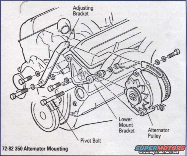
Exploded parts diagram of the 72-82 350 alternator mounting showing adjusting bracket, lower mount bracket and pivot bolt.
Part of 1968-1982 Chevrolet Corvette Exploded Parts Diagrams
This document is an exploded parts diagram showing the alternator mounting arrangement for 1972-1982 Chevrolet models equipped with the 350 engine, as stated in the caption "72-82 350 Alternator Mounting." The line-art illustration depicts the front of the engine with the alternator, its brackets, and all associated fasteners pulled apart along their assembly axes. Four callouts identify the key components: the Adjusting Bracket (the curved slotted arm at the top used to set belt tension), the Lower Mount Bracket (the main support bracket bolted to the engine), the Alternator Pulley (on the alternator's front shaft), and the Pivot Bolt (the long bolt on which the alternator swings during belt adjustment). Numerous bolts, washers, and spacers are shown in exploded fashion so a reader can see the correct order and orientation of hardware when removing or reinstalling the alternator and its brackets. No part numbers, torque specifications, or textual instructions are included; the value of the document is purely visual, it shows how the alternator mounting hardware assembles on a 350-equipped Corvette of this era. It was uploaded to an album of similar Corvette reference diagrams for a 1977 Chevrolet Corvette.
Is this accurate? Sign in to help verify it.
Frequently asked questions
- What years and engine does this alternator mounting diagram cover?
- The diagram's caption states it applies to 1972-1982 models with the 350 engine ("72-82 350 Alternator Mounting").
- What components are labeled in the alternator mounting diagram?
- The callouts identify the Adjusting Bracket, Lower Mount Bracket, Alternator Pulley, and Pivot Bolt.
- Does the diagram show how the alternator brackets and bolts fit together?
- Yes, it is an exploded view showing the alternator, adjusting bracket, lower mount bracket, pivot bolt, and associated bolts and washers pulled apart along their assembly axes so the hardware order is visible.
- Are torque specs or part numbers given in this diagram?
- No. The document contains only the exploded illustration and four component labels; no torque values or part numbers are shown.
Comments
More from this build

No comments yet.