1976-77 Chevy Corvette Radio & Dash Components Exploded Parts Diagram
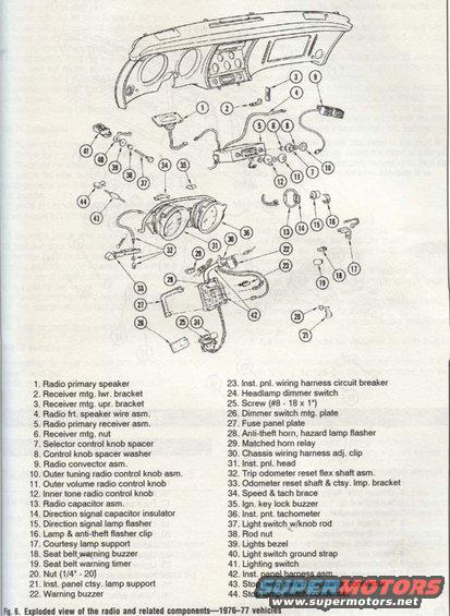
Exploded diagram (Fig. 5) of 1976-77 radio and related instrument-panel components with a 40+ item numbered legend covering radio, speakers, flashers, switches, tachometer, and harness clips.
Part of 1968-1982 Chevrolet Corvette Exploded Parts Diagrams
This document is an exploded parts diagram (Fig. 6) showing the radio and related instrument panel components for 1976-77 vehicles, uploaded to a 1977 Chevrolet Corvette gallery. The illustration depicts the dash/instrument panel assembly disassembled, with 44 numbered callouts identifying each component. The accompanying legend names every part, including the radio primary speaker and receiver assembly, mounting brackets and nuts, radio control knobs (outer tuning, outer volume, inner tone), radio capacitor assembly, direction signal lamp flasher, anti-theft horn and hazard lamp flasher, seat belt warning buzzer and timer, warning buzzer, instrument panel wiring harness circuit breaker, headlamp dimmer switch and mounting plate, fuse panel plate, matched horn relay, chassis wiring harness clip, trip odometer reset flex shaft assembly, speed & tach brace, ignition key lock buzzer, instrument panel tachometer, light switch with knob rod, lights bezel, lighting switch, ground strap, instrument panel harness assembly, and stop lamp switch capacitor connector and condenser. Fastener specifications listed include a 1/4"-20 nut (item 20) and a #8-18 x 1" screw (item 25). A reader can use this to identify, locate, and name radio and dash electrical components when disassembling or restoring the instrument panel on a 1976-77 vehicle.
Is this accurate? Sign in to help verify it.
Frequently asked questions
- What years does this radio components diagram cover?
- The caption states it shows an exploded view of the radio and related components for 1976-77 vehicles.
- What radio control knobs are identified in the diagram?
- It lists the outer tuning radio control knob assembly (item 10), the outer volume radio control knob (item 11), and the inner tone radio control knob (item 12), plus a selector control knob spacer (7) and control knob spacer washer (8).
- Which flashers and relays are shown on the instrument panel?
- The diagram identifies the direction signal lamp flasher (15), the lamp & anti-theft flasher clip (16), the anti-theft horn, hazard lamp flasher (28), and the matched horn relay (29).
- What fastener sizes are specified in the legend?
- Item 20 is a 1/4"-20 nut and item 25 is a #8-18 x 1" screw.
- What seat belt warning components are shown?
- The seat belt warning buzzer (item 18) and the seat belt warning timer (item 19), along with a general warning buzzer (item 22).
Comments
More from this build

No comments yet.