Home/
Registry/
Ford/
Mustang/
2005-2014/
“SHELBY GT500”/
Photo
supermotors.net/registry/media/655634
Ford 4x4 Front Suspension Exploded Parts Diagram - Hub, Axle Shaft, Control Arms

Reference · 2005-2014 MustangAll 44 exploded parts diagrams
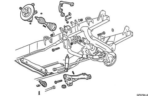
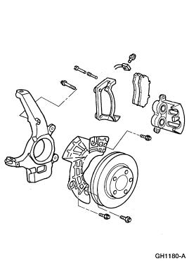
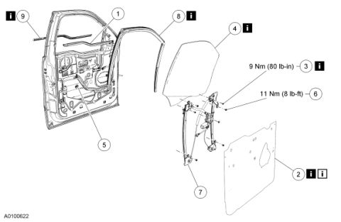
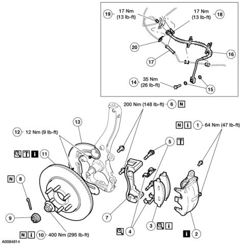
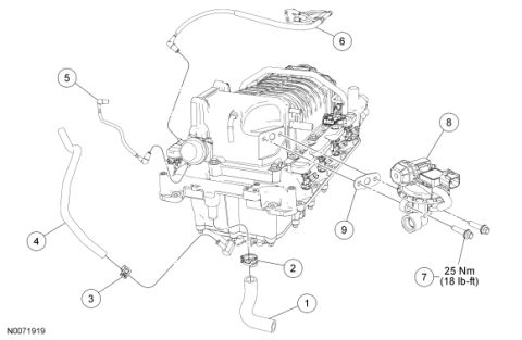









Exploded parts diagram of a front suspension showing control arms, shock absorber, and springs mounted to the frame.
Part of 2005-2014 Ford Mustang Exploded Parts Diagrams
This document is an exploded-view parts illustration (Ford illustration reference GF0794-A) showing front suspension and four-wheel-drive (4x4) front axle components on a truck frame. The line drawing depicts, in disassembled relation, a front hub/rotor assembly with wheel studs, a CV/axle half-shaft with boot, an upper control arm with ball joint and mounting bolts, the frame crossmember and front axle carrier/differential housing, a shock absorber, a torsion bar or stabilizer components, a lower control arm with bushings and pivot bolt, and assorted fasteners (bolts, nuts, washers) shown in their installation positions. No part numbers, torque specifications, legend, callout numbers, or text labels are present in the scan other than the Ford graphic identifier 'GF0794-A' in the lower right corner. The diagram is useful for visualizing how the independent front suspension and 4x4 front drive components fit together and the order of assembly, but it does not by itself identify individual part numbers or service specifications. It was uploaded to a gallery associated with a 2007 Ford Mustang, but the content clearly depicts a 4x4 truck front suspension, consistent with the many F-150-related documents in the same album.
Is this accurate? Sign in to help verify it.
Frequently asked questions
- What does this diagram show?
- An exploded view of a 4x4 front suspension/axle assembly, including the hub/rotor, CV axle shaft with boot, upper and lower control arms, shock absorber, front differential/axle housing, frame section, and related fasteners.
- Does the diagram include part numbers or torque specs?
- No. The only text visible is the Ford illustration reference 'GF0794-A'; there are no part numbers, torque values, or callout labels.
- What is the illustration reference number on this diagram?
- GF0794-A, printed in the lower right corner.
- Can I see how the upper control arm mounts from this diagram?
- Yes, the exploded view shows the upper control arm with its ball joint and mounting bolts positioned above the frame bracket, indicating assembly orientation.






No comments yet.