Home/
Registry/
Ford/
Mustang/
2005-2014/
“SHELBY GT500”/
Photo
supermotors.net/registry/media/655637
Ford 5.4L V8 Engine Exploded Diagram - Water Pump, Oil Filter, Rear Seal, Flywheel

Reference · 2005-2014 MustangAll 44 exploded parts diagrams
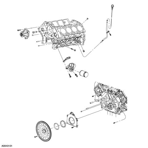
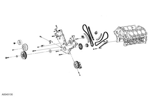
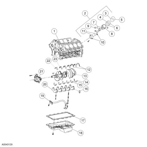
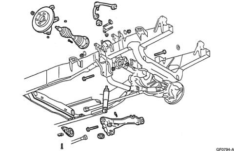
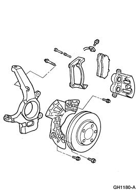









Exploded parts diagram of an engine block showing water pump, oil filter, flywheel, and dipstick.
Part of 2005-2014 Ford Mustang Exploded Parts Diagrams
This document is an exploded parts diagram illustrating a Ford V8 engine (labeled in the uploader's album as a 5.4L engine, page 3 of a multi-page set). The upper illustration shows the engine block assembly viewed from the front, with the water pump and its mounting bolts exploded away from the front cover area, the engine oil level indicator (dipstick) and dipstick tube with retaining bolt at the upper right, and the oil filter adapter, oil filter, and thermostat/water outlet components exploded below the block with their fasteners. The lower illustration shows the rear of the engine assembly with the rear main crankshaft seal and retainer plate, associated gaskets/O-rings, mounting bolts, and the flywheel/flexplate exploded away from the crankshaft rear flange. The only text in the document is the Ford illustration reference number 'A0043131' in the lower-left corner; no part numbers, torque specifications, callout legends, or year/model applicability statements are printed on this page. A reader can learn the relative assembly positions and orientation of the water pump, dipstick tube, oil filter and adapter, rear main seal retainer, and flywheel on this engine, but must consult accompanying pages or a service manual for fastener torques and part numbers.
Is this accurate? Sign in to help verify it.
Frequently asked questions
- What engine components are shown in this exploded diagram?
- The diagram shows the water pump and bolts, engine oil dipstick and tube, oil filter and oil filter adapter with fasteners at the front of the block, and the rear main seal retainer plate, seals/O-rings, and flywheel/flexplate at the rear of the engine.
- Does this diagram include torque specs or part numbers?
- No. The only text visible on the document is the illustration reference number A0043131; no torque values, part numbers, or callout legend are printed on this page.
- How is the flywheel installed according to the diagram?
- The lower illustration shows the flywheel/flexplate mounting over the rear crankshaft flange, behind the rear main seal retainer plate and its seals, with mounting bolts exploded in line with the crankshaft.
- Where does the oil dipstick tube attach in this illustration?
- The dipstick and its tube are shown at the upper right of the front engine view, routing down to the side of the engine block where the tube is secured with a bolt.






No comments yet.