Home/
Registry/
Ford/
Mustang/
2005-2014/
“SHELBY GT500”/
Photo
supermotors.net/registry/media/942869
Ford Supercharger Bolt Tightening Sequence Diagram (Fig. N0049439)

Reference · 2005-2014 MustangAll 52 service procedures
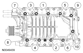
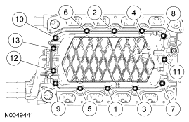
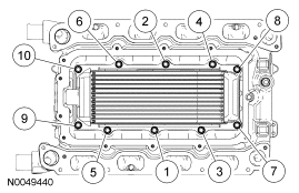
Torque-sequence diagram showing the numbered bolt tightening order for a supercharger assembly.
Part of 2005-2014 Ford Mustang Service Procedures
This document is a single service-procedure illustration (figure number N0049439) depicting a supercharger assembly mounted atop an engine intake area. The diagram uses ten circled numbered callouts (1 through 10) pointing to bolt locations around the perimeter of the supercharger housing, arranged with callouts 7, 3, 1, 5, and 9 along the top edge and 8, 4, 2, 6, and 10 along the bottom edge. This numbering pattern, alternating from the center outward, is characteristic of a fastener tightening (torque) sequence used when installing the supercharger onto the engine. The image contains no accompanying text, torque specifications, part numbers, or captions, only the numbered callouts and the figure reference number. A reader can learn the correct order in which to tighten (or loosen, in reverse) the supercharger mounting bolts: starting with the center bolts (1, 2), then working outward alternately (3, 4, 5, 6) and finishing with the outermost bolts (7, 8, 9, 10). The scan was uploaded to a 2007 Ford Mustang gallery, suggesting it applies to a supercharged Mustang engine (e.g., Shelby GT500 5.4L), though the document itself does not state a year, model, or engine.
Is this accurate? Sign in to help verify it.
Frequently asked questions
- What does this diagram show?
- It shows a supercharger mounted on an engine with ten numbered circled callouts (1-10) marking bolt positions, indicating the fastener tightening sequence.
- What is the bolt tightening order shown?
- The callouts run 1 through 10, starting with the two center bolts (1 on top, 2 on bottom) and alternating outward: 3, 4, 5, 6, then the outer bolts 7, 8, 9, and 10.
- Does the diagram give torque specifications?
- No. The image contains only the numbered callouts and the figure number N0049439; no torque values or text instructions are visible.
- What is the figure reference number for this illustration?
- N0049439.
No comments yet.