Home/
Registry/
Ford/
Mustang/
2005-2014/
“SHELBY GT500”/
Photo
supermotors.net/registry/media/659695
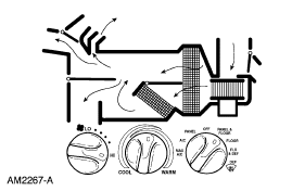
Ford Manual HVAC Control Panel & Airflow Schematic (AM2267-A) - Mode Positions
Reference · 2005-2014 MustangAll 19 schematics
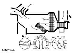
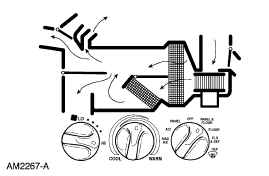
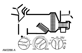
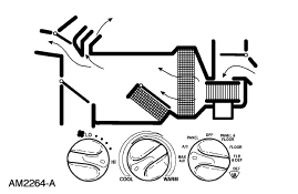
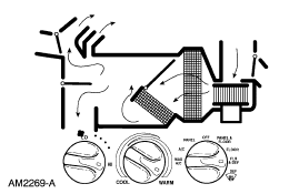
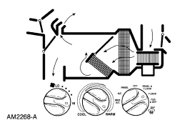









HVAC heater-control schematic illustrating airflow routing through the climate box with mode and temperature dials.
Part of 2005-2014 Ford Mustang Schematics
This document is a Ford HVAC (heating, ventilation, and air conditioning) reference schematic, illustration number AM2267-A. The upper portion shows a cutaway airflow diagram of the climate control plenum/air distribution box, with arrows tracing air paths from the intake through the blower, past the heater core/evaporator section, and out to the various vents (panel registers, floor outlets, and defroster ducts). The lower portion depicts the manual climate control panel with its three rotary knobs: a blower speed knob (marked LO with graduated speed positions), a temperature blend knob (marked COOL to WARM), and a mode selector knob with positions for PANEL, OFF, PANEL & FLOOR, FLOOR, FLR & DEF, DEF, and A/C (snowflake symbol). A reader can learn how the mode selector positions correspond to airflow routing inside the plenum, useful for diagnosing blend door, mode door, or airflow problems in a Ford manual HVAC system. The document itself carries no year, model, or part number identification beyond the Ford illustration number AM2267-A, so its exact vehicle applicability cannot be confirmed from the image alone.
Is this accurate? Sign in to help verify it.
Frequently asked questions
- What are the mode selector positions shown on this Ford HVAC control panel?
- The mode knob shows PANEL, OFF, PANEL & FLOOR, FLOOR, FLR & DEF, DEF, and an A/C (snowflake) position.
- What does the temperature knob range show?
- The center temperature knob rotates between COOL and WARM.
- What is the Ford illustration number on this schematic?
- The illustration is labeled AM2267-A.
- What does the upper part of the diagram illustrate?
- A cutaway airflow schematic of the HVAC plenum showing air paths (arrows) through the blower, heater core/evaporator area, and out to the panel, floor, and defrost outlets.






No comments yet.