Home/
Registry/
Ford/
Mustang/
2005-2014/
“SHELBY GT500”/
Photo
supermotors.net/registry/media/659693
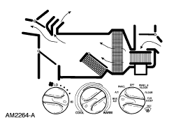
Ford Manual HVAC Airflow & Control Knob Diagram (AM2264-A) - Heater/AC Schematic
Reference · 2005-2014 MustangAll 19 schematics
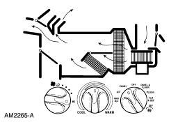
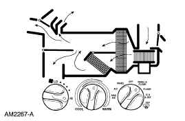
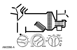
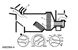
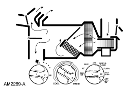
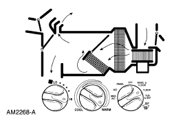
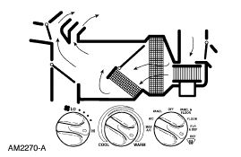
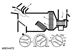









Schematic of HVAC airflow routing through the heater/AC case and ducts with control-knob settings.
Part of 2005-2014 Ford Mustang Schematics
This document is a Ford reference schematic (illustration number AM2264-A) depicting the airflow and control layout of a manual heater/air-conditioning (HVAC) system. The upper portion is a cutaway airflow diagram showing hatched arrows tracing air paths through the heater/A-C plenum assembly and ducting, illustrating how air is routed to the instrument panel (dash) registers, windshield defroster outlets, and floor ducts. The lower portion shows the three rotary knobs of the climate control head: a blower fan speed knob marked from LO to HI, a temperature blend knob marked COOL to WARM, and a function (mode) selector knob with positions including MAX A/C, A/C, OFF, and floor/panel/defrost combinations such as PANEL & FLOOR, FLOOR, FLOOR & DEF, and DEF. A reader can learn how the manual HVAC controls correspond to the air distribution paths inside the plenum, useful for diagnosing blend door, mode door, or airflow problems. The document carries no year, model, or engine designation of its own; it was uploaded to a 2007 Ford Mustang gallery, but the surrounding album contents suggest it belongs to a set of Ford truck (F-150 era) reference diagrams. The image is a small, low-resolution GIF, so fine label text is only partially legible.
Is this accurate? Sign in to help verify it.
Frequently asked questions
- What does this diagram show?
- It shows the airflow paths through the heater/air-conditioning plenum and ducting, plus the three rotary HVAC control knobs: fan speed (LO to HI), temperature (COOL to WARM), and the function/mode selector.
- What positions are on the mode selector knob?
- Legible positions include MAX A/C, A/C, OFF, and panel/floor/defrost combinations such as PANEL & FLOOR, FLOOR, and DEF; some labels are too small to read with certainty.
- What is the illustration reference number on this schematic?
- The diagram is labeled AM2264-A in the lower left corner.
- Does the diagram identify a specific vehicle year or model?
- No. The only text identifying the document is the illustration number AM2264-A; no year, model, or engine is stated on the diagram itself.






No comments yet.