Home/
Registry/
Ford/
Mustang/
2005-2014/
“SHELBY GT500”/
Photo
supermotors.net/registry/media/659692
Ford Manual HVAC Airflow Diagram - Floor/Defrost Mode & Control Knobs (AM2269-A)

Reference · 2005-2014 MustangAll 19 schematics
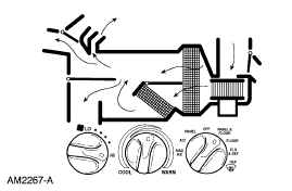
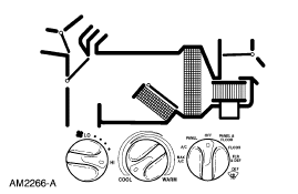
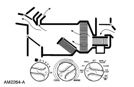
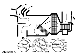
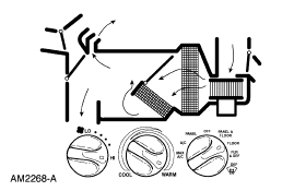
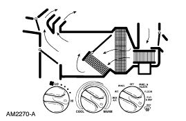
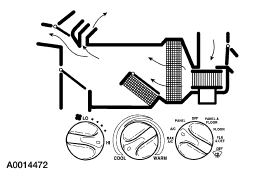









Schematic of HVAC airflow routing through the heater/AC case and ducts with control-knob settings.
Part of 2005-2014 Ford Mustang Schematics
This document is a small automotive HVAC (heating, ventilation, and air conditioning) reference schematic, identified by the Ford illustration number AM2269-A. The main portion of the image is a cutaway/flow diagram of a heater-A/C plenum assembly, with bold arrows showing how air moves through the blower, evaporator/heater core area, and out through the various duct outlets (defroster, panel, and floor outlets). Based on the upload filename ('floordef'), the arrows appear to depict the floor/defrost airflow mode. Below the airflow diagram are three manual HVAC control knobs: a fan (blower) speed knob on the left, a temperature knob in the center marked COOL through WARM, and a function/mode selector knob on the right marked with positions including OFF, A/C, and floor/defrost-type modes (most position labels are too small to read with certainty). A reader can learn from this document how air is routed through the climate control housing in a given mode and how the manual control head knobs correspond to that airflow. The image contains no year, model, or engine identification; it comes from a gallery of Ford truck reference material despite being filed under a 2007 Mustang.
Is this accurate? Sign in to help verify it.
Frequently asked questions
- What does this diagram show?
- It is a schematic showing airflow through a Ford heater/air conditioning plenum, with arrows indicating the air path through the housing and out to the outlets, plus the three manual HVAC control knobs (fan speed, temperature, and mode selector).
- What are the temperature knob markings?
- The center temperature knob is marked from COOL to WARM.
- What controls are pictured below the airflow diagram?
- Three rotary knobs: a fan/blower speed knob on the left, a COOL-WARM temperature knob in the center, and a function/mode selector knob on the right that includes OFF and A/C positions.
- Is there an identifying reference number on the diagram?
- Yes, the illustration is labeled AM2269-A in the lower left corner.






No comments yet.