1978 Ford Bronco Chassis Electrical Wiring Diagram - Fuse Box & Wire Colors
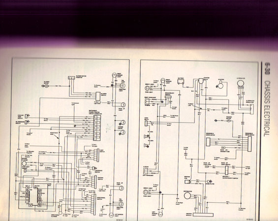
Scanned chassis-electrical manual page detailing blower motor, lighting, ignition, and wiper wiring circuits with color codes.
This document is a two-page chassis electrical wiring diagram (page 6-30, titled "CHASSIS ELECTRICAL") scanned from a printed service manual, drawing numbers 85766101 and 85766102. The left page covers interior/rear circuits: blower motor and resistor, blower switch, instrument panel printed circuit connector (with all wire colors listed), coolant temperature and oil pressure switches, hazard flasher, stop light switch, light switch, low brake switch, ignition switch, directional (turn signal) switch, directional flasher, and rear lighting (tail, back-up, direction, license, and marker lights). It also includes a fuse box legend showing fuse positions and amperages: INST LT 3A, HEATER 30A, FUEL TANK 15A, RADIO 7.5A, SEAT BELT 7.5A, B/U WIPER 15, ACC 20A, DIRECT 15, CTSY/CIG 15, and HAZ/STOP LT 20A. The right page covers front-end and engine circuits: battery, starter and starter relay, alternator and regulator, headlights and beam select switch, horn relay and horns, windshield wiper motor and switch, washer motor, back-up light switch, neutral/clutch safety switch, ignition coil, noise filter, distributor, and ignition module, with fusible link and 15A back-up/washer and back-up light fuses. Wire color codes (e.g., BLK/YEL, RED/GRN, BLU/RED) are labeled throughout, making this useful for tracing circuits on a late-1970s Ford Bronco or truck.
Is this accurate? Sign in to help verify it.
Frequently asked questions
- What are the fuse box positions and amperages shown in this wiring diagram?
- The fuse box legend lists: INST LT 3A, HEATER 30A, FUEL TANK 15A, RADIO 7.5A, SEAT BELT 7.5A, B/U WIPER 15, THROTTLE SOL, ACC 20A, DIRECT 15, CTSY/CIG 15, and HAZ/STOP LT 20A. There is also a 15A back-up/washer fuse and a 15A back-up light fuse shown in the circuit diagram.
- What wire colors go to the blower switch?
- The blower switch is shown with RED/BLK, BLU/RED, and BLK/YEL wires, and the blower motor connects via a BLK/YEL wire through the blower motor resistor (H, M, L terminals).
- Which circuits are covered on this page?
- It covers chassis electrical circuits including the blower motor, instrument panel printed circuit connector, lighting (headlights, tail, back-up, direction, marker, license lights), light switch, directional switch and flashers, hazard flasher, ignition switch, starter and starter relay, alternator and regulator, horn relay, windshield wiper/washer, ignition coil, distributor, ignition module, and neutral/clutch safety switch.
- What wire colors connect the ignition switch in this diagram?
- The ignition switch is shown with RED/BLU, RED/GRN, BLK/GRN, and YEL wires; a BLK/YEL wire runs from the starter relay area to the ignition switch on the right page.
- What protects the back-up and washer circuits?
- The diagram shows a 15A BACK-UP / WASHER FUSE and a separate 15A BACK-UP LIGHT FUSE, and a fusible link is shown near the starter relay/battery feed.
Comments
More from this build


No comments yet.