Battle Born Brakes Hydroboost Install Pg 4 - Bench Bleeding & Hose Routing Diagram
Reference · 1978-1979 BroncoAll 48 service procedures
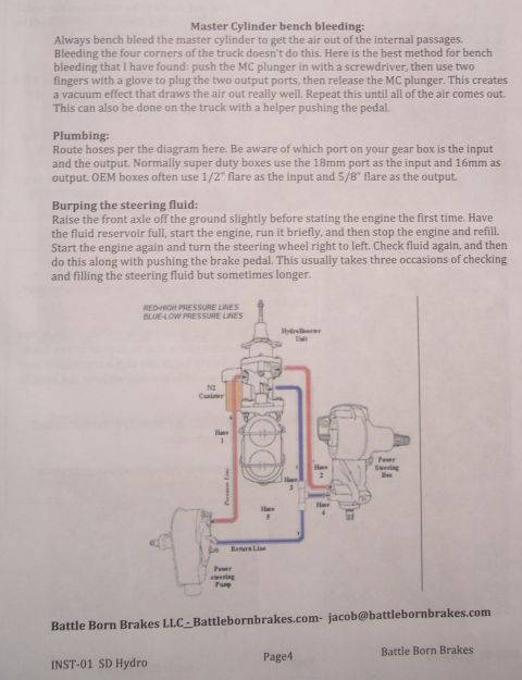
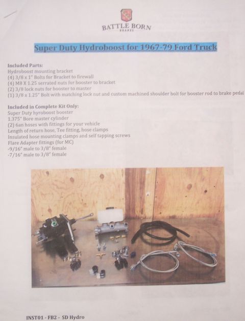
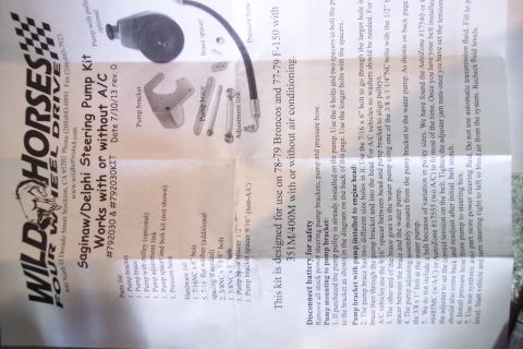
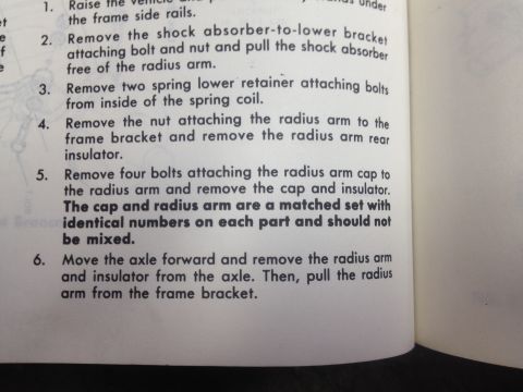
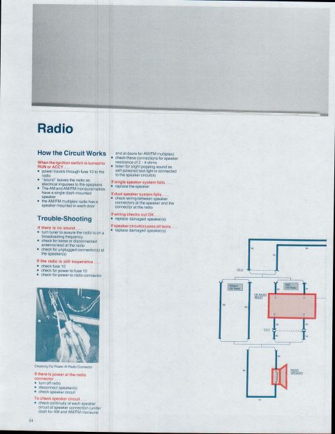

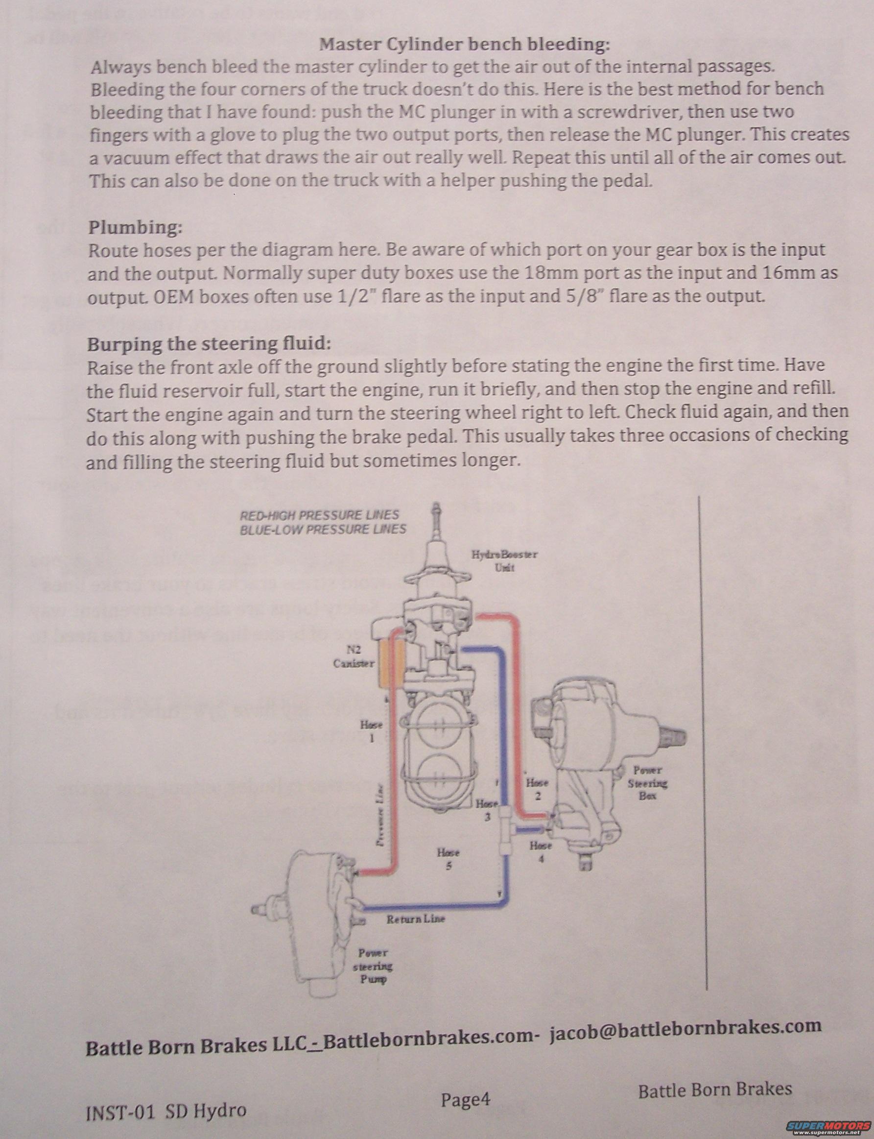
Battle Born Brakes hydroboost install page with plumbing diagram: super duty gear boxes use 18mm input and 16mm output, OEM boxes 1/2in input and 5/8in output; bench-bleed the master cylinder before installation.
Part of 1978-1979 Ford Bronco Service Procedures
This is page 4 of a Battle Born Brakes LLC installation instruction set (document code INST-01 SD Hydro) for a hydroboost (HydroBooster) brake conversion. It covers three procedures. First, master cylinder bench bleeding: push the MC plunger in with a screwdriver, plug the two output ports with gloved fingers, then release the plunger to create a vacuum that draws air out; repeat until all air is removed. Second, plumbing: route hoses per the included diagram, noting that Super Duty steering boxes normally use the 18mm port as input and 16mm as output, while OEM boxes often use 1/2" flare as input and 5/8" flare as output. Third, burping the steering fluid: raise the front axle, fill the reservoir, run the engine briefly, refill, then cycle the steering wheel right to left and press the brake pedal, typically requiring three or more fill/check cycles. The hose routing diagram shows the HydroBooster unit with N2 canister, power steering pump, and power steering box connected by Hoses 1-5, a pressure line, and a return line, with red indicating high-pressure lines and blue indicating low-pressure lines. Contact information for Battle Born Brakes (Battlebornbrakes.com, [email protected]) is printed at the bottom.
Is this accurate? Sign in to help verify it.
Frequently asked questions
- How do I bench bleed the master cylinder for the hydroboost install?
- Push the MC plunger in with a screwdriver, plug the two output ports with two gloved fingers, then release the plunger. This creates a vacuum that draws the air out. Repeat until all air is out. It can also be done on the truck with a helper pushing the pedal.
- Which port on the steering gear box is the input and which is the output?
- Super duty boxes normally use the 18mm port as the input and the 16mm port as the output. OEM boxes often use 1/2" flare as the input and 5/8" flare as the output.
- How do I burp the steering fluid after installing the hydroboost?
- Raise the front axle slightly off the ground before first start, fill the reservoir, start and run the engine briefly, stop and refill. Start again, turn the steering wheel right to left, check fluid, then repeat while also pushing the brake pedal. It usually takes three fill/check occasions, sometimes longer.
- What do the red and blue lines in the hose routing diagram mean?
- Red indicates high pressure lines and blue indicates low pressure lines.
- What components are shown in the plumbing diagram?
- The HydroBooster unit with N2 canister, the power steering pump, the power steering box, Hoses 1 through 5, a pressure line, and a return line.
No comments yet.