Home/
Registry/
Ford/
Mustang/
2005-2014/
“SHELBY GT500”/
Photo
supermotors.net/registry/media/670930
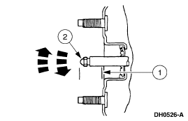
Ford Brake Booster Mounting Stud Diagram DH0526-A - Service Illustration
Reference · 2005-2014 MustangAll 52 service procedures
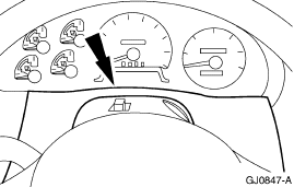
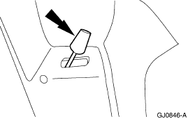
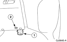
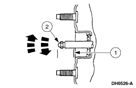
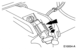
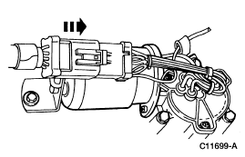
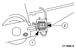
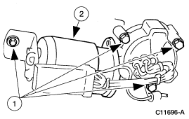









Service-manual line illustration (DH0526-A) showing a stud-mounted component with numbered callouts and directional arrows.
Part of 2005-2014 Ford Mustang Service Procedures
This document is a single service-procedure illustration (Ford illustration ID DH0526-A) uploaded under the filename 'booster.gif'. The image shows a close-up cutaway/side view of a flanged component mounted to a panel or housing, with threaded studs projecting through it at the top and bottom. Two numbered callouts are present: callout 1 points to the flanged component/bracket area, and callout 2 points to a small stud or fastener at the center left, with three sets of bold directional arrows indicating the direction of installation or removal for that item. No legend, part names, part numbers, torque specifications, or descriptive text accompany the callouts in this scan, so the identity of items 1 and 2 cannot be confirmed from the document alone. Based on the filename, the illustration likely relates to a brake booster mounting or stud installation step, but the document itself contains no year, model, or system identification beyond the Ford-style illustration number DH0526-A. Readers can learn the visual orientation of the components and the direction in which the callout-2 fastener is driven, but must consult the accompanying service text (not included) for procedure details.
Is this accurate? Sign in to help verify it.
Frequently asked questions
- What does illustration DH0526-A show?
- It shows a flanged component (callout 1) mounted through a panel with threaded studs, and a small stud/fastener (callout 2) with arrows indicating the direction it is installed or removed.
- How many callouts are in this diagram?
- Two callouts: item 1 pointing to the flanged component/mounting area, and item 2 pointing to a small stud or fastener.
- Does this document include torque specs or part numbers?
- No. The only text visible is the callout numbers 1 and 2 and the illustration ID DH0526-A; no torque values, part names, or part numbers are shown.
- Which direction is item 2 installed or removed?
- Bold arrows in the diagram point from left toward the component, indicating item 2 is driven horizontally toward the mounting flange.






No comments yet.