Home/
Registry/
Ford/
Mustang/
2005-2014/
“SHELBY GT500”/
Photo
supermotors.net/registry/media/692158
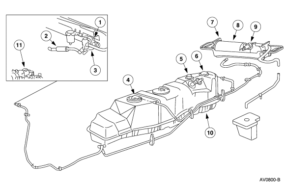
Ford EVAP System & Fuel Tank Component Diagram - Canister & Line Routing AV0800-B
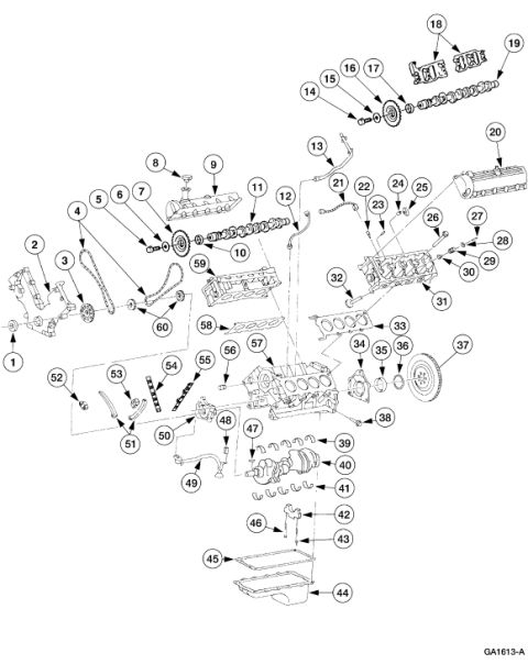
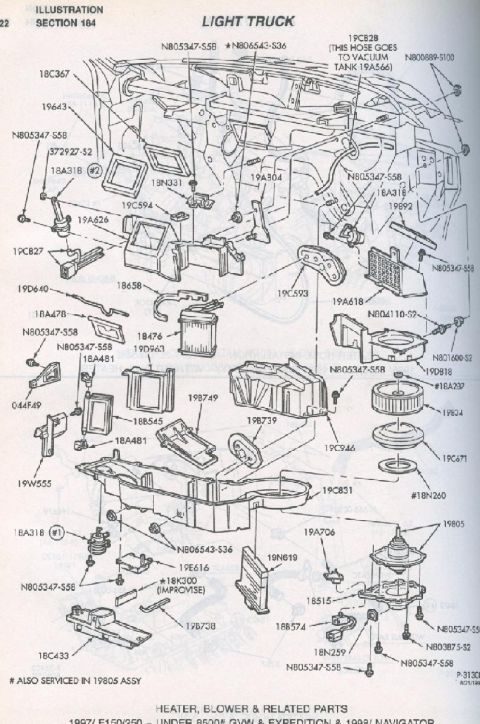
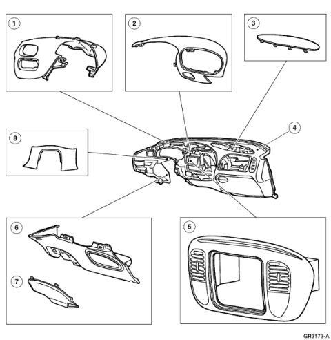
Reference · 2005-2014 MustangAll 44 exploded parts diagrams
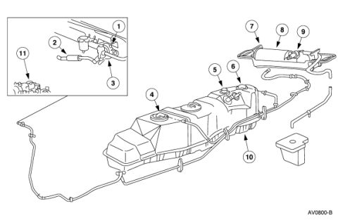









Exploded parts illustration of a fuel tank, fuel and vapor lines, and charcoal canister assembly with numbered callouts.
Part of 2005-2014 Ford Mustang Exploded Parts Diagrams
This document is a Ford factory-style illustration (figure code AV0800-B) depicting an exploded/component layout of a truck fuel tank and its associated evaporative emission (EVAP) and fuel line routing. Eleven numbered callouts identify components, though no legend or component names are printed on this page. The main view shows a mid-frame-mounted fuel tank with fuel filler and vent hoses, tube routing along the tank, a fuel pump/sender flange area (callouts 4-6), and a tank shield or support area (callout 10). An inset detail box at upper left enlarges a fitting/valve area on the frame or tank top (callouts 1-3 and 11), and a separate assembly at upper right, appearing to be the EVAP canister with attached valve and bracket, carries callouts 7-9. A reader can use this diagram to visually locate EVAP and fuel system components and their hose routing relative to the fuel tank, but must consult the accompanying service-manual legend (not included in this scan) to identify each numbered part by name or part number. No year, model, engine, part numbers, or torque values are stated in the image itself.
Is this accurate? Sign in to help verify it.
Frequently asked questions
- What does this diagram show?
- It shows an exploded/component illustration of a fuel tank with fuel and vapor line routing, an inset detail of fittings/valves (callouts 1-3, 11), a pump/sender area (callouts 4-6), a canister-style assembly (callouts 7-9), and a shield area (callout 10).
- How many components are called out in the diagram?
- Eleven numbered callouts (1 through 11) are shown, plus the figure reference code AV0800-B.
- Does the diagram include a parts legend or part numbers?
- No. Only the callout numbers and the figure code AV0800-B are printed; there is no legend, part names, or part numbers on this page.
- Where is the EVAP canister assembly shown in the diagram?
- The canister-style assembly appears at the upper right of the diagram, identified by callouts 7, 8, and 9.






No comments yet.