Home/
Registry/
Ford/
Mustang/
2005-2014/
“SHELBY GT500”/
Photo
supermotors.net/registry/media/690131
Ford Transfer Case Exploded Parts Diagram - Component Callouts (C11717-B)

Reference · 2005-2014 MustangAll 44 exploded parts diagrams
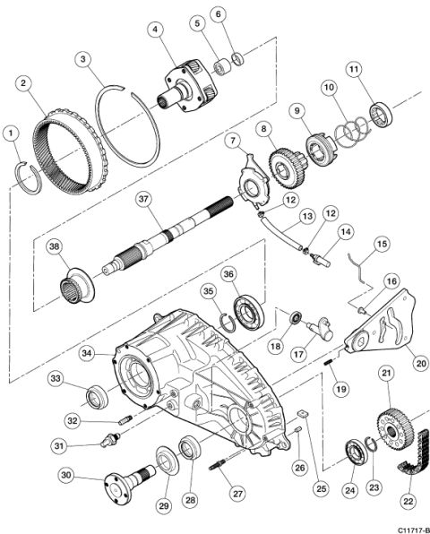









Exploded parts breakdown of a transfer case assembly with planetary gearset, mainshaft, drive chain, and housing numbered 1 through 38.
Part of 2005-2014 Ford Mustang Exploded Parts Diagrams
This document is an exploded-view parts illustration of a transfer case assembly, labeled with figure code C11717-B. It contains no written legend, table, or part names, only numbered callouts (1 through 38, with callout 12 appearing twice) pointing to individual components. The illustration depicts the main transfer case housing (callout 34) at center, with components arranged along diagonal assembly axes: a large ring/annulus gear and snap rings (1-3), a planetary carrier or front output assembly with bearing and seal (4-6), a shift fork or collar and geared hub/synchronizer-style parts (7-11), the main shaft (37) with a splined gear (38), small clips, a sensor or switch and bracket hardware (12-20), a chain drive sprocket and drive chain with bearing and snap ring (21-24), fasteners and small hardware (25-27, 31-32), output shaft flange/yoke with seals and bearing (28-30, 33), and internal bearing, snap ring, and seal components (17-18, 35-36). A reader can use this diagram to identify the relative position and assembly order of transfer case components by callout number, though a separate legend is required to match numbers to part names or part numbers.
Is this accurate? Sign in to help verify it.
Frequently asked questions
- What does this diagram show?
- It is an exploded-view illustration of a transfer case assembly, showing how components such as the case housing, gears, shafts, bearings, seals, snap rings, drive chain, and sprockets fit together, identified by numbered callouts 1 through 38.
- Does the diagram include part names or part numbers?
- No. The only text in the document is the numbered callouts (1-38) and the figure reference code C11717-B in the bottom right corner. No legend or parts list is included.
- How many numbered components are identified in the diagram?
- Callouts numbered 1 through 38 are shown, with callout 12 appearing twice, pointing to different small parts.
- What is the figure reference code on this diagram?
- The code printed in the lower right corner is C11717-B.






No comments yet.