Home/
Registry/
Ford/
Mustang/
2005-2014/
“SHELBY GT500”/
Photo
supermotors.net/registry/media/689479
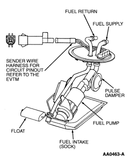
Ford In-Tank Fuel Pump & Sender Assembly Diagram - Sock, Float, Pulse Damper
Reference · 2005-2014 MustangAll 44 exploded parts diagrams
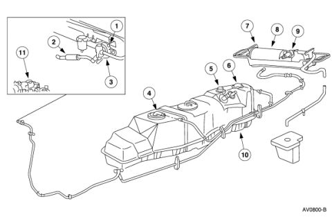
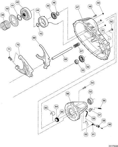
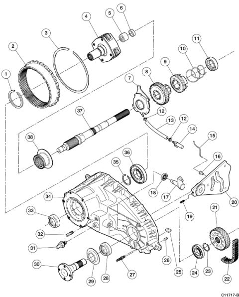
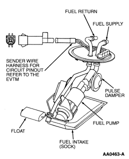
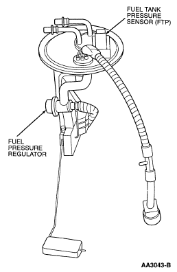
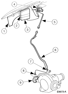
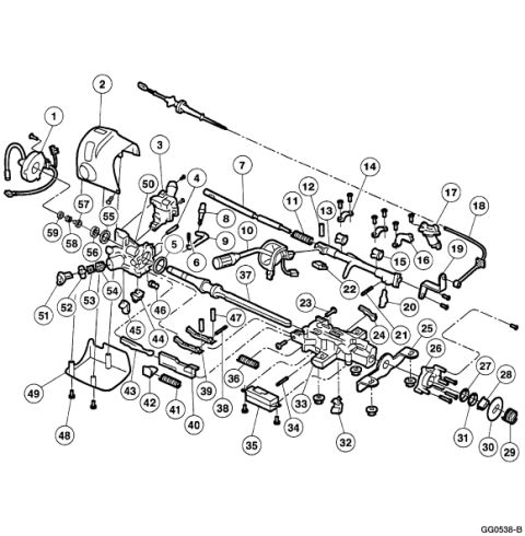









Cutaway parts illustration of an in-tank fuel pump assembly with float, fuel intake sock, pulse damper, and fuel supply/return.
Part of 2005-2014 Ford Mustang Exploded Parts Diagrams
This document is a labeled exploded/line-art illustration of an in-tank fuel pump and sender assembly. The drawing shows the assembly hanging from its circular tank flange, with callouts identifying the major components: the fuel return line and fuel supply line at the top of the flange, the sender wire harness (with a note directing the reader to the EVTM, Electrical and Vacuum Troubleshooting Manual, for the circuit pinout), the pulse damper mounted on the assembly, the fuel pump itself, the float on its arm for the fuel level sender, and the fuel intake sock (strainer) at the bottom of the pump. The illustration reference number AA0463-A appears in the lower right corner. From this diagram a reader can learn the physical layout and relative positions of the fuel pump module components, which port is supply versus return, where the pulse damper sits, how the float arm extends from the assembly, and that the intake sock filters fuel entering the pump. No year, model, torque values, part numbers, or wiring pinouts are given in the drawing itself; electrical details are deferred to the EVTM.
Is this accurate? Sign in to help verify it.
Frequently asked questions
- What components are labeled on this fuel pump assembly diagram?
- The diagram labels the fuel return, fuel supply, sender wire harness, pulse damper, float, fuel pump, and fuel intake (sock).
- Where can I find the circuit pinout for the fuel sender wire harness?
- The diagram states to refer to the EVTM (Electrical and Vacuum Troubleshooting Manual) for the sender wire harness circuit pinout.
- Where is the fuel intake sock located on the assembly?
- The fuel intake (sock) is shown at the bottom of the fuel pump, where fuel is drawn into the pump.
- What is the illustration reference number on this diagram?
- The illustration is marked AA0463-A in the lower right corner.






No comments yet.