Home/
Registry/
Ford/
Mustang/
2005-2014/
“SHELBY GT500”/
Photo
supermotors.net/registry/media/695049
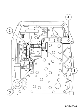
Ford Transmission Valve Body Diagram AD1405-A - Component Callout Illustration
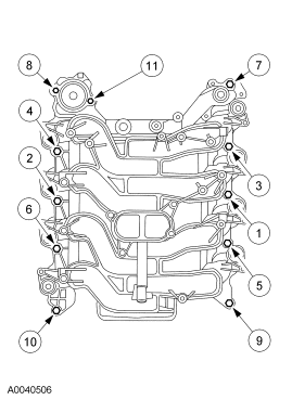
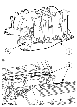
Reference · 2005-2014 MustangAll 44 exploded parts diagrams
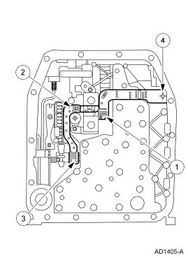
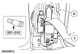

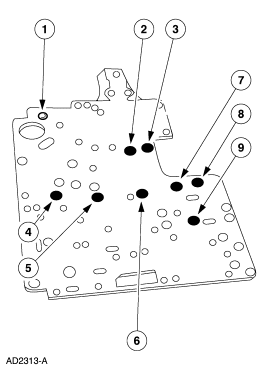
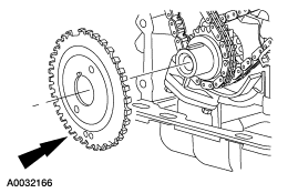
Service-manual component diagram of a transmission valve body with numbered callouts.
Part of 2005-2014 Ford Mustang Exploded Parts Diagrams
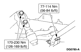
This document is a single-page line-art illustration (figure number AD1405-A) showing what appears to be an automatic transmission valve body or control body assembly viewed from one face. Four numbered callout balloons (1 through 4) point to specific components on the assembly, such as solenoids, a spring-loaded valve area, and mounting points, but no legend or component name list is included on this page, so the identity of each numbered item cannot be determined from this scan alone. No part numbers, torque specifications, wire colors, or textual descriptions appear in the image other than the callout numbers and the Ford-style illustration reference code AD1405-A. The scan was uploaded to a 2007 Ford Mustang gallery, but the surrounding album contains many Ford F-150 and 4R70W/4R100 transmission diagrams, suggesting this figure likely belongs to a Ford service manual set for a truck automatic transmission rather than specifically to the Mustang. A reader can use this diagram to visually locate the four referenced components on the valve body, provided they have the accompanying legend page from the same manual set.
Is this accurate? Sign in to help verify it.
Frequently asked questions
- What does this diagram show?
- It is a line-art illustration (figure AD1405-A) of an automatic transmission valve body assembly with four numbered callouts pointing to specific components.
- How many components are called out in the diagram?
- Four numbered callouts (1, 2, 3, and 4) are shown pointing to different areas of the assembly.
- Does the diagram identify the parts by name or part number?
- No. Only the callout numbers 1-4 and the illustration code AD1405-A are visible; there is no legend, part list, or part numbers on this page.
- What is the illustration reference number on this figure?
- AD1405-A, printed at the bottom right of the diagram.
No comments yet.