Home/
Registry/
Ford/
Mustang/
2005-2014/
“SHELBY GT500”/
Photo
supermotors.net/registry/media/704006
Ford 4.6L V8 Intake Manifold & Gasket Exploded Parts Diagram (A0013524)
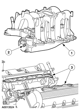
Service/parts illustration showing the intake manifold and its position on the engine with numbered callouts.
This document is a black-and-white exploded parts illustration showing an intake manifold assembly for an overhead-cam V8 engine. The upper portion of the drawing shows the complete intake manifold assembly (callout 1) with its throttle body or attached component at the front (callout 2). The lower portion of the drawing shows the intake manifold gaskets (callout 3) positioned on the left-bank cylinder head/valve cover area of the engine, illustrating gasket placement during removal or installation. Arrows indicate the orientation and mating relationships of the parts. The only text visible in the scan is the three numeric callout balloons (1, 2, 3) and the Ford illustration reference number A0013524 in the lower left corner. No legend, part numbers, torque specifications, or year/model applicability text is present in this scan, so the identification of specific components must be inferred from the drawing itself. Based on the uploader's filename ('4.6 intakw.gif'), the illustration is intended to depict the intake manifold for a Ford 4.6L modular V8 engine, but the document itself does not state this. A reader can learn the general arrangement of the intake manifold, its front-mounted component, and the location of the intake gaskets relative to the cylinder head.
Is this accurate? Sign in to help verify it.
Frequently asked questions
- What does this diagram show?
- It is an exploded parts illustration showing an intake manifold assembly (callout 1), a component mounted at the front of the manifold such as the throttle body (callout 2), and the intake manifold gaskets positioned on the cylinder head (callout 3).
- Where do the intake manifold gaskets go?
- Callout 3 in the lower view shows the gaskets seated on the intake ports of the cylinder head, beneath where the intake manifold mounts.
- Does the diagram include torque specs or part numbers?
- No. The only text visible is the callout numbers 1, 2, and 3 and the illustration reference number A0013524; no torque values, part numbers, or legend are shown.
- What engine is this intake diagram for?
- The document itself does not state the engine. The drawing depicts an overhead-cam V8 intake manifold, and the file was uploaded as '4.6 intakw.gif', suggesting a Ford 4.6L engine.
Comments
More from this build












No comments yet.