Home/
Registry/
Mercury/
Grand Marquis/
1992-1997/
“The "LSE S/C"”/
Photo
supermotors.net/registry/media/799970
1992 Lincoln Town Car Anti-Theft System Wiring Diagram - Alarm Circuits & Colors
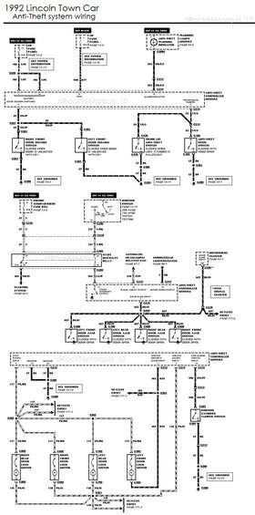
1992 Lincoln Town Car anti-theft system wiring diagram showing modules, fuses, switches and connector wire codes.
Part of 1992-1997 Mercury Grand Marquis Wiring Diagrams
This scan is a complete anti-theft (security) system wiring diagram for the 1992 Lincoln Town Car, annotated by dRock96Marquis (2010). It is drawn in three sections. The top section shows power feeds to the Anti-Theft Controller Module: a 20A I/P fuse panel fuse (hot at all times, circuit 195 T/W to battery/door disarm switch pins), a 15A fuse hot in run (640 R/Y), and the anti-theft warning indicator in the warning lamps module (343 DB/LG). It also covers the right and left front door disarm switches (25 DG/P, closed when unlocked with key), trunk lid anti-theft switch, and anti-theft hood switch (23 T/LG). The middle section shows the ignition switch feed (25A engine compartment fuse, 37 Y / 137 Y/BK), the start interrupt relay (325 DB/O to starting system, 342 LG/P), flash lights output (218 W/P), sound horn output (1 DB), and the four door ajar switches on circuit 627 BK/O with instrument cluster and keyless entry interfaces. The bottom section details lock/unlock outputs: 117 PK/BK to all four door lock motors, 118 PK/O and 163 R/O to keyless entry, and the ignition cylinder tamper switch (936 DG/W). Ground points G200, G203, G207, G213 and splice/connector IDs are labeled with page references to the factory EVTM.
Is this accurate? Sign in to help verify it.
Frequently asked questions
- What fuses power the 1992 Lincoln Town Car anti-theft system?
- A 20A fuse in position 11 of the I/P fuse panel (hot at all times, circuit 195 T/W), a 15A fuse in position 6 (hot in run, circuit 640 R/Y), and a 25A fuse (position P) in the engine compartment fuse box feeding the ignition switch (circuit 37 Y).
- What wire color are the door ajar switch circuits?
- All four door ajar switches (left/right front and rear) use circuit 627 BK/O (black/orange), joining at splice S259 and feeding the anti-theft controller module's door ajar input (pin 3) and the keyless entry system.
- Which wires control the door lock motors?
- Lock side is circuit 117 PK/BK from the controller's lock doors input (pin 9) via splices S260 and S262 to all four door lock motors; the unlock/return side is circuit 118 PK/O joining at S261, with 163 R/O for the unlock driver's door input.
- When do the trunk lid and hood anti-theft switches close?
- The trunk lid anti-theft switch closes when the lock cylinder is pulled out, and the anti-theft hood switch closes when the hood is open; both use circuit 23 T/LG to the controller's trunk/hood tamper input (pin 5).
- How does the anti-theft system interrupt starting?
- The controller's start interrupt output (pin 11, circuit 342 LG/P) controls a start interrupt relay in the ignition switch start circuit (137 Y/BK); circuit 325 DB/O then continues to the starting system (page 20-1).
Comments
More from this build





No comments yet.