Home/
Registry/
Ford/
Bronco/
1992-1996/
1994 Ford Bronco/
Photo
supermotors.net/registry/media/486211
1994 Ford Bronco/F-Series 5.0L Fuel Pump Wiring Diagram - Engine Controls 24-8

Reference · 1992-1996 BroncoAll 411 wiring diagrams


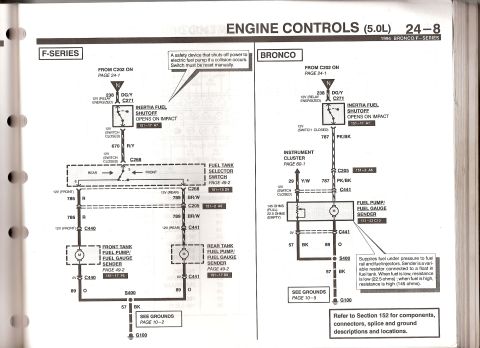
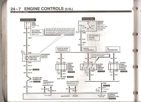
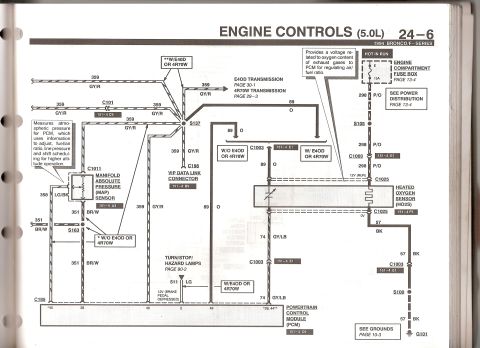
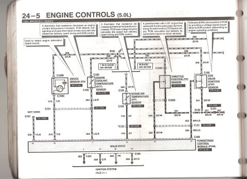
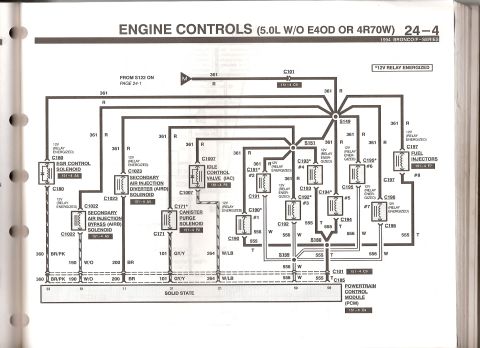
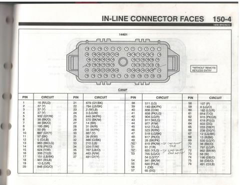
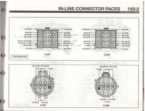
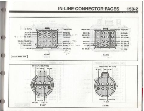






Ford 1994 Bronco/F-Series 5.0L engine-controls schematic (24-8): inertia fuel shutoff switch, fuel tank selector, front/rear fuel pumps and fuel-gauge senders; sender 22.5 ohms empty to 145 ohms full.
Part of 1992-1996 Ford Bronco Wiring Diagrams
This is page 24-8 of a 1994 Ford Bronco/F-Series factory wiring manual, covering the fuel pump wiring within the Engine Controls (5.0L) section. Two side-by-side schematics are shown: one for the F-Series (dual tank) and one for the Bronco (single tank). Both circuits begin at connector C202 (from page 24-1) with circuit 238 DG/Y feeding the Inertia Fuel Shutoff switch (which opens on impact and must be manually reset) via connector C271. On F-Series, power then flows on circuit 670 R/Y through C268 to the Fuel Tank Selector Switch, then via circuit 786 R (front tank) or 789 BR/W (rear tank) through C205, C440 and C441 to the front and rear tank fuel pump/fuel gauge senders, grounding through circuit 89 O to splice S400, 57 BK, and ground G100. On the Bronco, circuit 787 PK/BK passes through C205 and C441 to the combined fuel pump/fuel gauge sender, with circuit 29 Y/W to the instrument cluster; the sender is a variable resistor (22.5 ohms empty, 145 ohms full). Ground path is 57 BK/89 O through S400 to G100. Cross-references point to grounds pages 10-2/10-5, pages 49-2, 60-1, and Section 152 for connector locations.
Is this accurate? Sign in to help verify it.
Frequently asked questions
- What wire color feeds the inertia fuel shutoff switch on a 1994 Bronco/F-Series 5.0L?
- Circuit 238 DG/Y (dark green/yellow) from connector C202 feeds the inertia fuel shutoff switch through connector C271, with 12V present when the fuel pump relay is energized.
- What does the inertia fuel shutoff switch do?
- It is a safety device that shuts off power to the electric fuel pump if a collision occurs; the switch opens on impact and must be reset manually.
- What wire color goes to the fuel pump on a 1994 Bronco 5.0L?
- Circuit 787 PK/BK (pink/black) carries 12V from the inertia switch through connectors C205 and C441 to the fuel pump/fuel gauge sender. Ground is 57 BK and 89 O through splice S400 to ground G100.
- What are the fuel gauge sender resistance values on the 1994 Bronco?
- The sender is a variable resistor: 22.5 ohms when the tank is empty (low fuel) and 145 ohms when full (high fuel).
- Which circuits feed the front and rear tank fuel pumps on the 1994 F-Series dual-tank setup?
- From the fuel tank selector switch (via C268), circuit 786 R feeds the front tank pump through connector C440, and circuit 789 BR/W feeds the rear tank pump through connector C441.






No comments yet.