Home/
Registry/
Ford/
Bronco/
1992-1996/
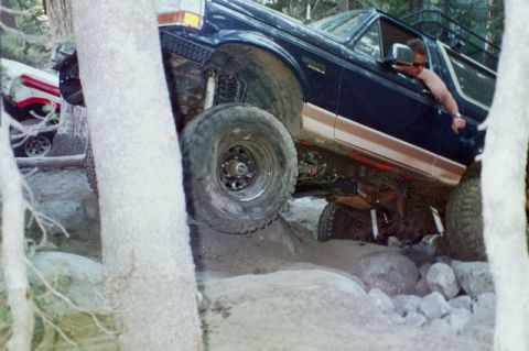
1996 Ford Bronco/
Photo
supermotors.net/registry/media/892442

This diagram illustrates the components of a typical in-tank fuel pump assembly, including the pump, sender, and float.
9A-5 very Systems FDS ery systems differ in design and arrangement depending upon the vehicle and model year. I nding and to simplify diagnostic instruction. they are classified as either Type 1 (Single Tank) k): Delivery Assembly Jr in-Tank Fuel Pump Assembly elivery Assembly (one assembly per tank) usly supply the fuel injectors with clean fuel at a controlled pressure, all systems require a fuel = check valve. a reservoir surrounding the pump inlet, a fine mesh fuel filter, a pressure and return system of tubes and hoses, a fuel tank, and a fuel supply manifold or fuel rail 'njectors. The Powertrain Control Module (POM) controls power input to the fuel delivery correct timing for the fuel injectors. for the Type 1 System p assembly (Figure 1) has a discharge check valve (to maintain system pressure during minimize starting problems), an inlet screen for protection and fuel return provision. The pump F has an additional fuel line tap used for draining the tank. PUMP POSITIVE SENDER POSITIVE F'UMP NEGATIVE FUEL SUPPLY SENDER GROUND GAUGE SENDEFI PULSE DAMPER FUEL PUMP A1 631 7-A Figure 1: Typical In-Tank Fuel Pump Assembly 1994 Powertrain Control/Emissions Diagnosis July, 1993
Comments
More from this build


No comments yet.