Home/
Registry/
Ford/
Bronco/
1992-1996/
1996 Ford Bronco/
Photo
supermotors.net/registry/media/892443
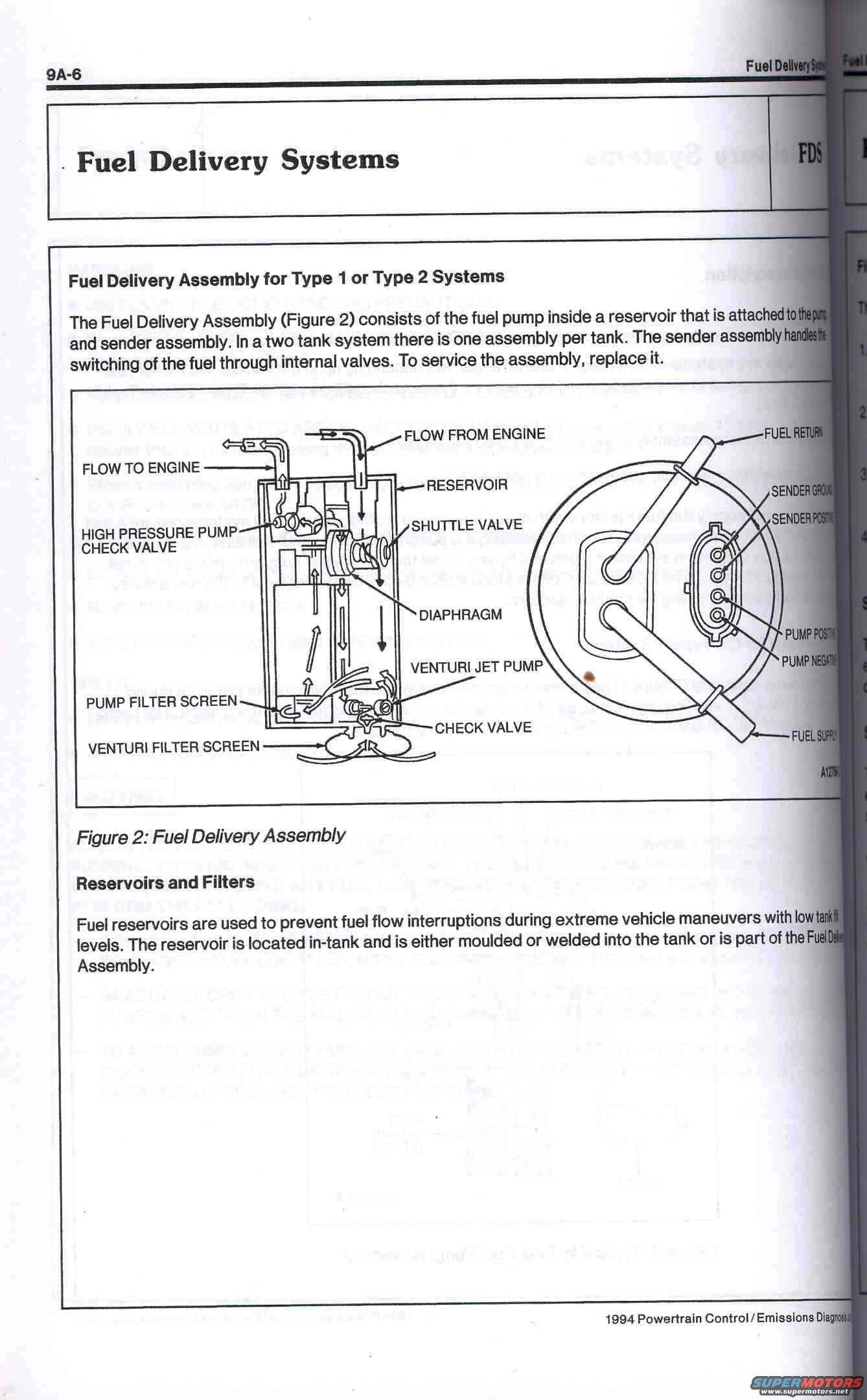
1994 Ford Fuel Delivery Assembly Diagram - In-Tank Pump & Reservoir (Page 9A-6)
Reference · 1992-1996 BroncoAll 98 manual pages
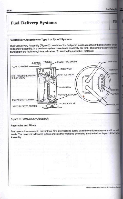









Service manual page on the Type 1/2 fuel delivery assembly with a labeled cutaway figure and reservoirs/filters description.
Part of 1992-1996 Ford Bronco Manual Pages
This is page 9A-6 from the 1994 Ford Powertrain Control / Emissions Diagnosis manual, covering the Fuel Delivery Systems (FDS) section. The page describes the Fuel Delivery Assembly used in Type 1 or Type 2 fuel systems, explaining that it consists of a fuel pump housed inside a reservoir attached to the pump and sender assembly. On two-tank systems there is one assembly per tank, and the sender assembly handles switching of fuel through internal valves; the assembly is serviced by replacement rather than repair. Figure 2 provides a labeled cutaway diagram of the assembly, identifying the flow-to-engine and flow-from-engine ports, reservoir, high pressure pump check valve, shuttle valve, diaphragm, venturi jet pump, pump filter screen, check valve, and venturi filter screen. A second illustration shows the top flange with the fuel return and fuel supply lines plus the electrical connector pins: sender ground, sender positive, pump positive, and pump negative. A short section on Reservoirs and Filters explains that fuel reservoirs prevent fuel flow interruptions during extreme vehicle maneuvers at low tank fill levels, and that the reservoir is in-tank, either moulded/welded into the tank or part of the Fuel Delivery Assembly.
Is this accurate? Sign in to help verify it.
Frequently asked questions
- What does the Fuel Delivery Assembly consist of?
- It consists of the fuel pump inside a reservoir that is attached to the pump and sender assembly. In a two tank system there is one assembly per tank.
- How is the Fuel Delivery Assembly serviced?
- The manual states that to service the assembly, you replace it; the sender assembly handles the switching of fuel through internal valves.
- What components are shown in the Fuel Delivery Assembly diagram (Figure 2)?
- The diagram labels the flow-to/from-engine ports, reservoir, high pressure pump check valve, shuttle valve, diaphragm, venturi jet pump, pump filter screen, check valve, venturi filter screen, fuel return, fuel supply, and the sender ground, sender positive, pump positive, and pump negative connector pins.
- What is the purpose of the in-tank fuel reservoir?
- Fuel reservoirs prevent fuel flow interruptions during extreme vehicle maneuvers with low tank fill levels. The reservoir is in-tank and is either moulded or welded into the tank or is part of the Fuel Delivery Assembly.






No comments yet.