1980-86 steering column exploded diagrams: base, tilt, auto and…
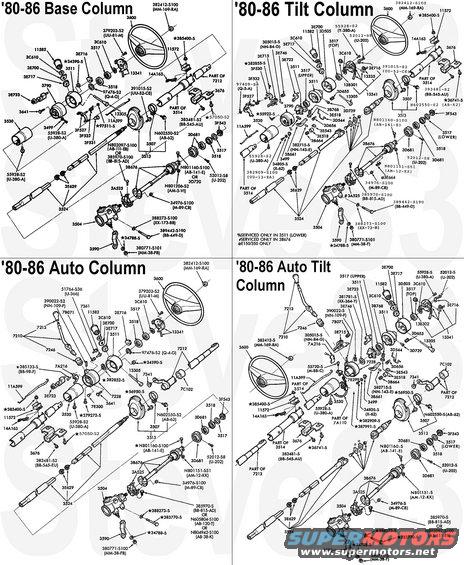
'80-86 Truck Steering Columns ('87-91 similar)
IF THE IMAGE IS TOO SMALL, click it.
The steering wheel, the bracket/tray 3676, and the intermediate shaft & rag joint (3B676) are the differences for '87-91. For '92-up columns, see this:
For tilt ignition actuators, see:
 .
.  .
. 
--------------------------------------------------------------------------------
TSB 95-23-12 Non-Tilt Key Hard to Turn in Cold
Publication Date: NOVEMBER 20, 1995
LIGHT TRUCK: 1988-91 BRONCO, ECONOLINE, F SUPER DUTY, F-150-350 SERIES
MEDIUM/HEAVY TRUCK: 1988-95 F & B SERIES
ISSUE: The ignition key may be hard to turn in cold temperatures on trucks equipped with fixed (non-tilt) steering columns. This occurs because the column lock actuator may not be properly lubricated.
ACTION: Lubricate the column lock actuator with silicone lubricant. Refer to the following procedures for service details.
REMOVAL
1. Disconnect the battery ground cable.
2. Remove the steering wheel. Refer to the appropriate model year Bronco, Econoline, F-Series Service Manual, Section 13-06 for 1988-90 models and Section 11-04A for 1991 models. Refer to the 1991 F-FT-B 600, 700, 800 Service Manual, Section 13-06 and Section 11-04A for 1992-95 F & B Series vehicles.
3. Remove the two (2) bolts attaching the steering column support brackets to the pedal support bracket.
4. Mark the location of the ignition switch and remove it.
5. Remove the turn signal lever and turn signal switch.
6. Remove the lock cylinder.
7. Remove and throw away the snap ring from the upper steering shaft.
8. Using a light hammer, gently tap the steering shaft until the upper bearing is loose. Remove the upper bearing.
9. Loosen the upper flange retention nuts until one or two threads remain engaged.
a. Pinch the nuts toward the shaft.
b. Remove the upper flange from the outer tube.
10. Remove the column lock actuator.
INSTALLATION
1. Clean the grease from the column lock actuator and upper flange using parts cleaner (F3AZ-19579-SA) or equivalent.
2. Apply silicone lubricant (COAZ-19553-AA) or equivalent to the column lock actuator and upper flange where the actuator slides.
3. Install the column lock actuator into the upper flange.
4. Install the upper flange onto the outer flange.
5. Install the steering wheel onto the steering shaft and hand tighten the steering wheel nut.
6. Pull up on the steering wheel until the steering column expands about 10mm (0.375").
7. Remove the steering wheel.
8. Press the upper bearing onto the steering shaft.
9. Install a new snap ring (DOAZ-3C610-B) on the steering shaft.
10. Using a small hammer, gently tap the steering shaft until the upper bearing is seated into the upper flange.
11. Install the lock cylinder.
12. Install the turn signal switch and turn signal lever.
13. Install the ignition switch.
14. Install the two (2) bolts attaching the steering wheel bracket to the pedal bracket.
15. Install the steering wheel.
16. Connect the battery ground cable.
PART NUMBER PART NAME
COAZ-19553-AA Silicone Lubricant
F3AZ-19579-SA Metal Brake Parts Cleaner
DOAZ-3C610-B Snap Ring
OTHER APPLICABLE ARTICLES: NONE
SUPERSEDES: 91-6-5
WARRANTY STATUS: Eligible Under Basic Warranty Coverage
OPERATION DESCRIPTION TIME
952312A Lubricate Actuator 0.7 Hr.
Ig.Sw. Recall
Is this accurate? Sign in to help verify it.
Comments
More from this build


No comments yet.