3-Position Rotary Selector Switch: Contact Positions #1 & #2 Diagram
Reference · 1993-1997 ProbeAll 27 brochures & literature














Sales listing image of a rotary selector switch labeled US SELLER, with thumbnail variants and contact-position diagrams.
Part of 1993-1997 Ford Probe Brochures & Literature
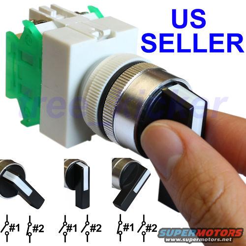
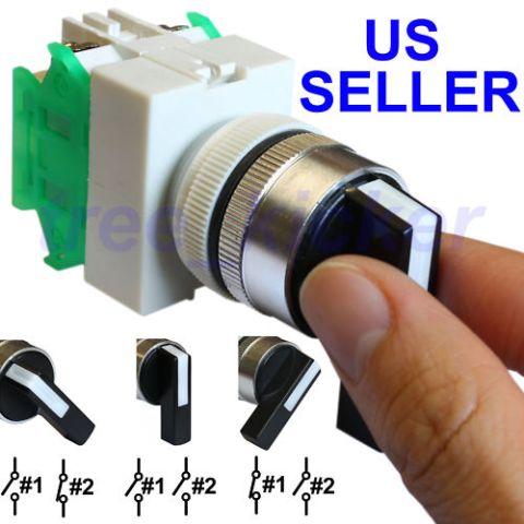
This is a seller's product photo (marked "US SELLER") of a panel-mount 3-position rotary selector switch, not a printed automotive reference document. The main image shows a hand turning the black selector knob of a chrome-bezel switch with a white plastic body and green contact block on the rear. Along the bottom are three smaller photos showing the knob in its three positions (left, center, right), each paired with a simple contact schematic for two circuits labeled #1 and #2. The schematics indicate that in the left position contact #1 is closed and #2 is open; in the center position both #1 and #2 are open; and in the right position #1 is open and #2 is closed. A reader can learn the switching logic of this maintained 3-position selector, which of the two contact blocks conducts in each knob position. No part numbers, voltage/current ratings, wire colors, or vehicle applicability information appear in the image. The image is watermarked "free_kicker," consistent with an online auction/eBay listing photo. It was uploaded to a 1993 Ford Probe gallery, but nothing in the image ties it to any specific vehicle.
Is this accurate? Sign in to help verify it.
Frequently asked questions
- How many positions does this selector switch have?
- Three. The bottom insets show the knob turned left, centered, and turned right, each with its own contact diagram.
- Which contacts are closed in each switch position?
- Per the diagrams: left position closes contact #1 (with #2 open), the center position leaves both #1 and #2 open, and the right position closes contact #2 (with #1 open).
- How many switched circuits does the switch control?
- Two circuits, labeled #1 and #2 in the contact schematics.
- Does the image give any electrical ratings or part numbers?
- No. The only text visible is "US SELLER," the watermark "free_kicker," and the #1/#2 contact labels, no ratings, part numbers, or wiring info.






No comments yet.