Tachometer Output from Coil Negative - 1N4004 Diode Rev Counter Schematic

Reference · 1993-1997 ProbeAll 25 schematics
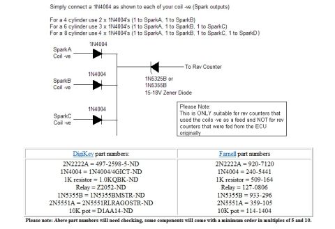
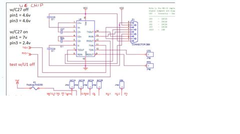
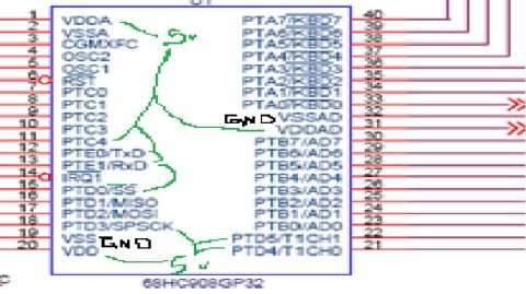
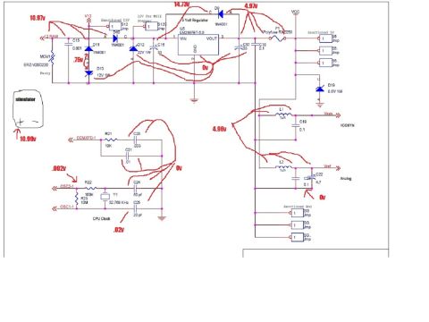
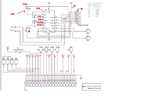
Schematic showing 1N4004 diodes wiring spark coil negatives to a rev counter, with DigiKey and Farnell part numbers.
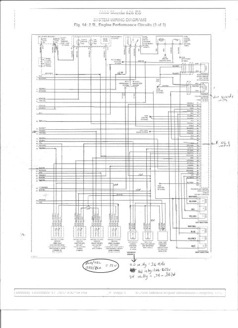
Part of 1993-1997 Ford Probe Schematics
This document is a simple electronics schematic showing how to create a tachometer (rev counter) output signal from ignition coil negative (-ve) terminals, typically when converting to a coil-per-cylinder or aftermarket ECU setup. It instructs connecting a 1N4004 diode to each coil's negative terminal (Spark output): two diodes for a 4-cylinder engine, three for a 6-cylinder, and four for an 8-cylinder. The diode outputs are joined and fed through a 15-18V Zener diode (1N5325B or 1N5355B) to the rev counter. A caution box notes this method is ONLY suitable for rev counters that were originally fed from the coil negative terminal, not for tachometers driven by the ECU. A parts table cross-references DigiKey and Farnell part numbers for the components: 2N2222A transistor, 1N4004 diode, 1K resistor, relay, 1N5355B Zener, 2N5551A transistor, and a 10K potentiometer. A footnote warns the part numbers need verification and some components have minimum order quantities of 5 or 10. The document itself is generic and undated; it was uploaded to a 1993 Ford Probe gallery, likely for use in an ECU/ignition conversion project.
Is this accurate? Sign in to help verify it.
Frequently asked questions
- How do I get a tach signal from coil negative terminals?
- Connect a 1N4004 diode to each coil's -ve (Spark output), join the diode outputs, and feed them through a 15-18V Zener diode (1N5325B or 1N5355B) to the rev counter.
- How many 1N4004 diodes do I need for my engine?
- 2 for a 4-cylinder (SparkA and SparkB), 3 for a 6-cylinder (SparkA, B, C), and 4 for an 8-cylinder (SparkA, B, C, D).
- Will this work with an ECU-driven tachometer?
- No. The document states this is ONLY suitable for rev counters that used the coils -ve as a feed, NOT for rev counters that were originally fed from the ECU.
- What Zener diode is used for the rev counter output?
- A 1N5325B or 1N5355B, 15-18V Zener diode.
- What are the DigiKey and Farnell part numbers for the 1N4004?
- DigiKey: 1N4004/4GICT-ND; Farnell: 240-5441. The document notes the part numbers need checking and some parts have minimum orders in multiples of 5 and 10.



No comments yet.