2000 Mazda 626 2.5L Engine Performance Wiring Diagram - PCM Pins & O2 Sensors

Reference · 1993-1997 ProbeAll 65 wiring diagrams

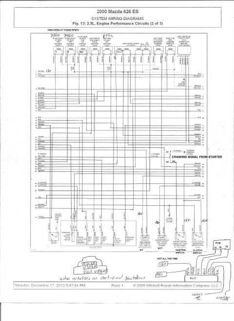
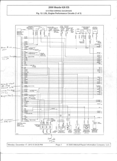
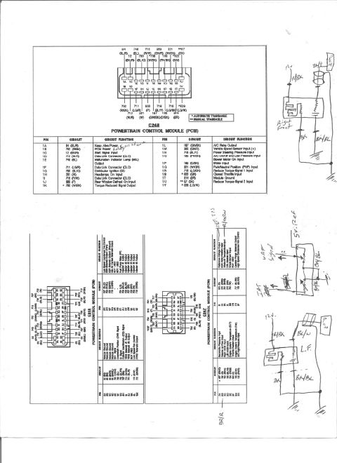
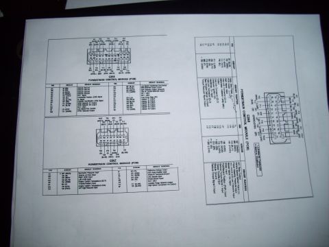
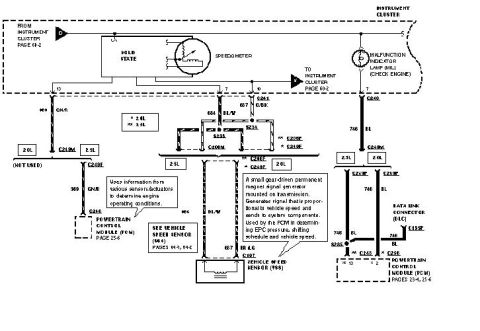
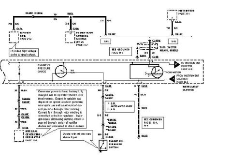
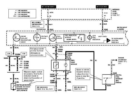









Mazda 626 ES 2.5L engine performance circuits system wiring diagram continuation with labeled components.
Part of 1993-1997 Ford Probe Wiring Diagrams
This document is a scanned page from Mitchell Repair Information system wiring diagrams for a 2000 Mazda 626 ES, specifically Fig. 14: 2.5L Engine Performance Circuits (3 of 3). It shows wiring for the Powertrain Control Module (PCM, located under the center console), including numbered pins 1-28 on one side and pins 71-104 on the other, each labeled with wire colors (e.g., pin 71 RED/BLK, pin 80 LT BLU, pin 91 BLK/YEL). Components covered include the instrument cluster (check engine and O/D off indicators), fuel pump relay on the main fuse block, fuel gauge sender unit in the fuel tank, input/turbine speed sensor on the left front of the transaxle, camshaft position sensor, four heated oxygen sensors (with 2000 California/Federal and 2001/2002 location variations), EGR boost sensor, throttle position sensor, fuel tank pressure sensor, and left and right fuel injector banks with pin numbers and wire colors. Stop fuse (15A) and meter fuse (15A) in the joint box behind the left side of the dash are shown, plus grounds G300, G206, and G101. Handwritten annotations mark 12V feeds (BLK/YEL and RED/BLK = 12V), an oxygen sensor input pin, and EGR boost sensor voltage-vs-vacuum test values.
This document covers 2000, which may differ from this 1993 Ford Probe.
Is this accurate? Sign in to help verify it.
Frequently asked questions
- Where is the PCM located on the 2000 Mazda 626 2.5L?
- The diagram identifies the Powertrain Control Module (PCM) location as under the center console.
- What are the EGR boost sensor voltage readings shown in the handwritten notes?
- 0.0 in. Hg = 3.6-4.4V, 16.1 in. Hg = 1.66-2.03V, and 24 in. Hg = 0.711-0.867V.
- Which wires carry 12V on this 2000 Mazda 626 diagram?
- A handwritten circled note states BLK/YEL and RED/BLK = 12V; several 12V callouts are also written along diagram branches.
- What fuses feed these engine performance circuits?
- The 15A STOP fuse and 15A METER fuse in the joint box behind the left side of the dash, on circuits hot in RUN or START.
- Where is the camshaft position sensor and what wire colors does it use?
- It is on the right front of the engine and uses BLU, BLK/RED, and PNK wires.






No comments yet.