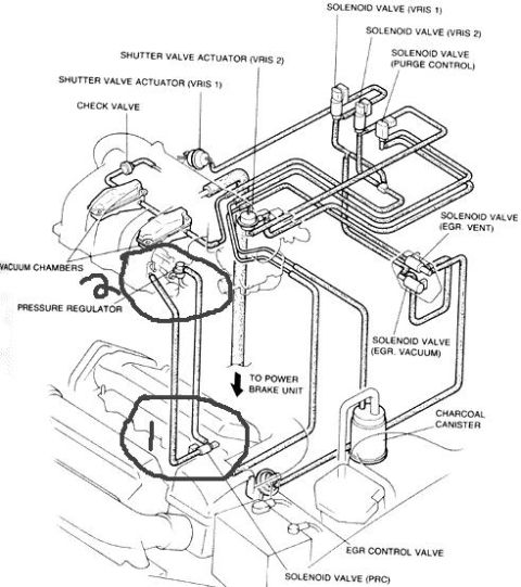
1993 Ford Probe Compound Turbo & Intercooler Plumbing Routing Diagram
Reference · 1993-1997 ProbeAll 9 vacuum routing diagrams

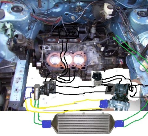
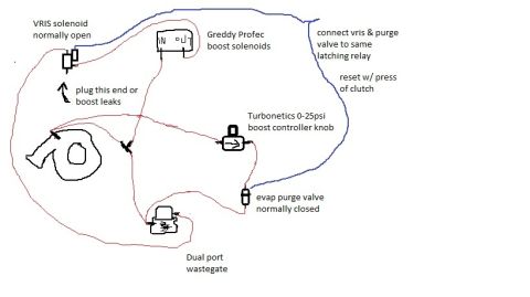
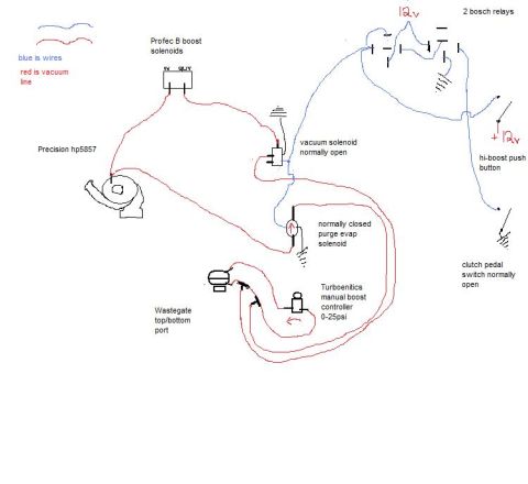
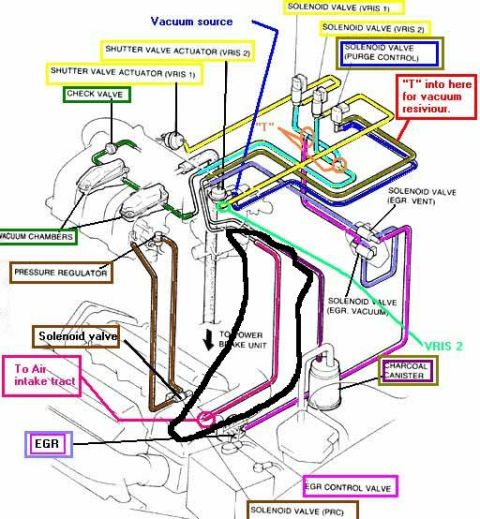
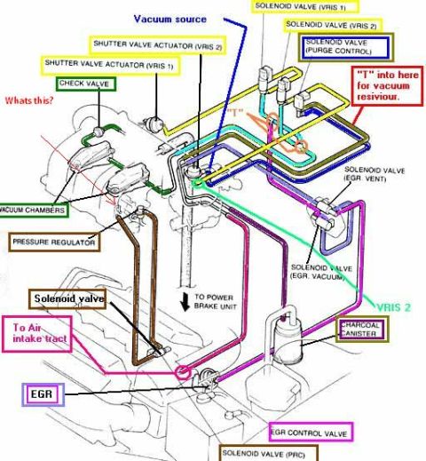
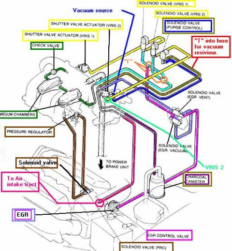
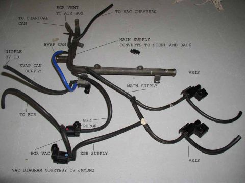









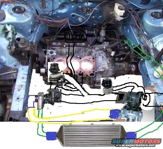
Underhood photo with colored overlay lines diagramming turbo, wastegate and intercooler charge-air piping for an engine build.
Part of 1993-1997 Ford Probe Vacuum Routing Diagrams
This document is not a printed reference page but a modified photograph of a front-wheel-drive engine bay (consistent with the uploader's Ford Probe) with hand-drawn overlay lines illustrating a planned turbocharger and intercooler plumbing layout, apparently a compound or twin-charged setup, per the filename 'compoun.jpg'. Superimposed on the photo are images of two turbochargers, two blow-off/wastegate-style valves, what appears to be a supercharger or additional compressor unit on the right, and a front-mount intercooler at the bottom. Black lines trace exhaust and charge-air routing between the components; a yellow line and green lines indicate additional plumbing paths (likely coolant, oil, or separate charge-pipe runs), with blue blocks representing silicone coupler connections at the intercooler end tanks and elsewhere. A small black box drawn at the top of the engine contains a marking that may read 'TDC'. Because the image contains essentially no legible text, a reader can learn only the conceptual routing of the compound forced-induction system the owner was planning or documenting, which components connect to which, and where the intercooler sits in the charge path, rather than any specifications, part numbers, or fuse/wiring data.
Is this accurate? Sign in to help verify it.
Frequently asked questions
- What does this diagram show?
- It is a photograph of an engine bay with hand-drawn lines showing planned routing between two turbochargers, valves, an additional compressor unit, and a front-mount intercooler, a compound forced-induction plumbing layout.
- Are there any part numbers or specifications in this document?
- No. The image contains no legible part numbers, torque values, fuse data, or specifications, only drawn routing lines and superimposed component images.
- What do the colored lines represent?
- The document does not include a legend. Black lines connect the turbos, valves, and intercooler; yellow and green lines show additional plumbing runs; blue blocks appear to mark coupler/connection points at the intercooler and piping.
- Where is the intercooler located in this layout?
- The intercooler is shown at the bottom front of the vehicle, with connections drawn to both end tanks (marked with blue blocks) linking it into the charge piping.






No comments yet.