1993-94 Ford Probe Engine Bay Component Location Diagram - Relays, Fans, Grounds
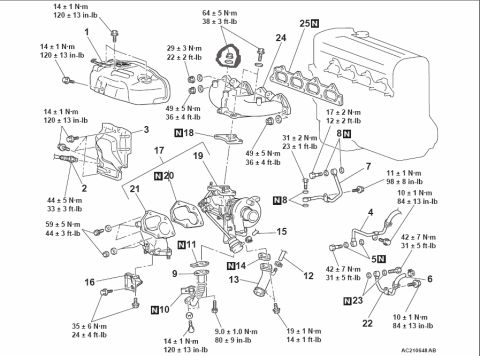
Reference · 1993-1997 ProbeAll 2 exploded parts diagrams










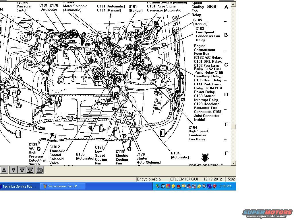
Underhood component locator for a 1994 Ford 4.6L engine bay showing positions of every relay (A/C, DRL, fog, fuel pump, headlamp, horn, park lamp, PCM power, starter) and the engine compartment fuse box.
Part of 1993-1997 Ford Probe Exploded Parts Diagrams
This document is a screenshot of an electronic service publication (file ERUCM187.GUI) showing an engine compartment component location diagram, apparently for a Ford Probe (uploaded to a 1993 Probe gallery, filename references '94'). The line drawing depicts the engine bay viewed from the front, with callout labels identifying connectors, grounds, and relays. Identified components include the Cycling Pressure Switch, C134/C170 Distributor, starter motor/solenoid locations for automatic (with C131 Pulse Signal Generator) and manual (C176) transmissions, ground points G101, G104, and G105 (with separate automatic/manual locations), the High Speed Cooling Fan Relay, C163 Low Speed Condenser Fan Relay, and C164 High Speed Condenser Fan Relay. A key callout details the Engine Compartment Fuse Box contents: C132 A/C Relay, C101 DRL Relay, C102 Fog Lamp Relay, C152 Fuel Pump Relay, C100 Headlamp Relay, C105 Horn Relay, C141 Park Lamp Relay, C104 PCM Power Relay, C160 Starter Interrupt Relay, C123 Headlamp Retractor Test Connector, and C169 Joint Connector. Also labeled are C129 A/C High Pressure Cutout/Fan Switch, C1012 Transaxle Control Solenoid Valve, C167 Low Speed Cooling Fan, and C118 Electric Cooling Fan. Grid letters A-F run along the right edge for locating components. No fuse amperages or wire colors are shown.
Is this accurate? Sign in to help verify it.
Frequently asked questions
- What relays are inside the Ford Probe engine compartment fuse box per this diagram?
- C132 A/C Relay, C101 DRL Relay, C102 Fog Lamp Relay, C152 Fuel Pump Relay, C100 Headlamp Relay, C105 Horn Relay, C141 Park Lamp Relay, C104 PCM Power Relay, C160 Starter Interrupt Relay, plus the C123 Headlamp Retractor Test Connector and C169 Joint Connector inside.
- Where are the condenser fan relays identified in this diagram?
- C163 is the Low Speed Condenser Fan Relay and C164 is the High Speed Condenser Fan Relay; both are called out near the right side of the engine bay by the fuse box area.
- Which connector is the A/C high pressure cutout/fan switch?
- C129, labeled 'A/C High Pressure Cutout/Fan Switch,' shown at the lower left front of the engine bay.
- What ground points are shown, and do they differ by transmission?
- Grounds G101, G104, and G105 are shown, with separate locations noted for automatic and manual transmissions (e.g., G101 Automatic / G104 Manual near the top, G105 Automatic and G105 Manual, and G104 Automatic near the front).
- What are the cooling fan connectors labeled in this diagram?
- C167 is the Low Speed Cooling Fan and C118 is the Electric Cooling Fan, both located at the front of the vehicle.






No comments yet.