Ford EEC-IV 60-Pin Connector Diagram - Mass Air Conversion Steps 7-8
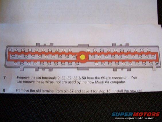
Service procedure showing a 60-pin connector diagram with numbered steps for removing terminals during a Mass Air computer conversion.
This document is a page from a Mass Air conversion instruction sheet (a service procedure for converting a Ford speed-density EEC-IV engine computer system to a Mass Air Flow system). The page features a color diagram of the 60-pin EEC-IV computer connector, showing all sixty pin positions arranged in three rows (1-20 on top, 21-40 in the middle, 41-60 on the bottom) with a yellow circle marking the central connector bolt. Below the diagram are two numbered instruction steps. Step 7 instructs the reader to remove the old terminals from pins 9, 33, 52, 58 and 59 of the 60-pin connector, noting these wires can be removed because they are not used by the new Mass Air computer. Step 8 begins instructions to remove the old terminal from pin 57 and save it for step 15, then install a new red wire (the sentence is cut off at the bottom of the scan). A reader can learn which EEC connector pins must be de-populated during a Mass Air conversion and how the 60-pin connector cavities are numbered.
Is this accurate? Sign in to help verify it.
Frequently asked questions
- Which terminals are removed from the 60-pin connector in this Mass Air conversion?
- Step 7 says to remove the old terminals 9, 33, 52, 58 & 59 from the 60-pin connector; these wires are not used by the new Mass Air computer and can be removed.
- What happens to the wire at pin 57?
- Step 8 says to remove the old terminal from pin 57 and save it for step 15, then install a new red wire (text cut off in the scan).
- How are the pins arranged in the 60-pin connector diagram?
- The diagram shows three rows: pins 1-20 across the top, 21-40 in the middle, and 41-60 along the bottom, with a yellow circle marking the center of the connector.
- Why can pins 9, 33, 52, 58 and 59 be removed?
- Per the document, those wires are not used by the new Mass Air computer.
Comments
More from this build
No comments yet.