Ford EEC-IV 60-Pin Connector Diagram - Mass Air Conversion Steps 7-8
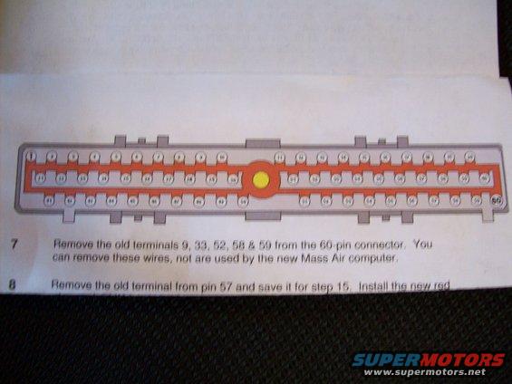
Service procedure showing a 60-pin connector diagram with numbered steps for removing terminals during a Mass Air computer conversion.
This document is a page from a Mass Air conversion instruction sheet (a service procedure for converting a Ford speed-density EFI system to mass air flow metering). It shows a large color illustration of the 60-pin EEC (engine computer) wiring harness connector, viewed face-on, with all sixty terminal positions numbered in three rows (1-20 top, 21-40 middle, 41-60 bottom) and the center bolt hole highlighted in yellow. Below the diagram are two numbered procedure steps. Step 7 instructs the installer to remove the old terminals at pins 9, 33, 52, 58 and 59 from the 60-pin connector, noting these wires can be removed because they are not used by the new Mass Air computer. Step 8 begins instructions to remove the old terminal from pin 57 and save it for step 15, then install a new red wire/terminal; the remainder of step 8 is cut off at the bottom of the scan. A reader can learn the pin numbering layout of the Ford 60-pin ECU connector and which pins are depopulated during a mass air conversion.
Is this accurate? Sign in to help verify it.
Frequently asked questions
- Which terminals are removed from the 60-pin connector during the Mass Air conversion?
- Step 7 says to remove the old terminals 9, 33, 52, 58 & 59 from the 60-pin connector; these wires are not used by the new Mass Air computer and can be removed.
- What should be done with the terminal in pin 57?
- Step 8 instructs to remove the old terminal from pin 57 and save it for step 15, then install the new red wire (remainder of the instruction is cut off in the scan).
- How are the pins arranged on the 60-pin connector in the diagram?
- The diagram shows three rows of numbered terminals: pins 1-20 across the top, 21-40 in the middle, and 41-60 along the bottom, with the connector's center bolt hole highlighted.
- Why can pins 9, 33, 52, 58 and 59 be removed?
- Because, per the document, those wires are not used by the new Mass Air computer.
Comments
More from this build
No comments yet.