Ford Alternator Clocking Diagram - 3:00, 7:00 & 11:00 Regulator Terminal Positions

Reference · 1987-1991 BroncoAll 95 service procedures

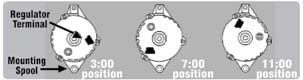












Service illustration showing alternator regulator terminal and mounting-spool clock positions at the 3:00, 7:00 and 11:00 orientations.
Part of 1987-1991 Ford Bronco Service Procedures
This document is a small illustrated diagram showing alternator "clocking", the rotational orientation of an alternator's rear housing relative to its mounting. Three rear-view drawings of the same alternator are shown side by side, each with the regulator terminal (electrical connector) rotated to a different position: 3:00 position, 7:00 position, and 11:00 position (described like clock-face positions). The leftmost drawing includes two callout labels: "Regulator Terminal," pointing to the connector on the rear of the alternator, and "Mounting Spool," pointing to the mounting boss/ear at the lower left of the case. The diagram lets a reader identify which clocking orientation their alternator has (or needs) by comparing the location of the regulator terminal against the three illustrated positions. This is useful when ordering a replacement alternator or re-clocking a rebuilt unit so the connector and mounting spool line up correctly with the vehicle's bracket and wiring harness. The image contains no part numbers, year/model applicability, torque specs, or written procedure text, only the three position illustrations and the two component callouts. It was uploaded to a 1990 Ford Bronco gallery as a service/reference aid, though the diagram itself states no vehicle applicability.
Is this accurate? Sign in to help verify it.
Frequently asked questions
- What alternator clocking positions are shown in this diagram?
- Three positions are illustrated: 3:00 position, 7:00 position, and 11:00 position, based on where the regulator terminal sits on the rear of the alternator.
- How do I identify my alternator's clock position?
- Compare the location of the regulator terminal on the back of your alternator to the three drawings; the position (3:00, 7:00, or 11:00) corresponds to a clock-face location relative to the mounting spool.
- What parts of the alternator are labeled in the diagram?
- Two callouts are labeled: the Regulator Terminal (the connector on the rear of the alternator) and the Mounting Spool (the mounting boss on the lower left of the case).
- Does this document list part numbers or vehicle years?
- No. The diagram contains only the three position illustrations and the labels; no part numbers, years, or model applicability are shown.






No comments yet.