Locating TDC for Distributor Installation - Ford V8 & I6 Valve Overlap Method
Reference · 1987-1991 BroncoAll 95 service procedures













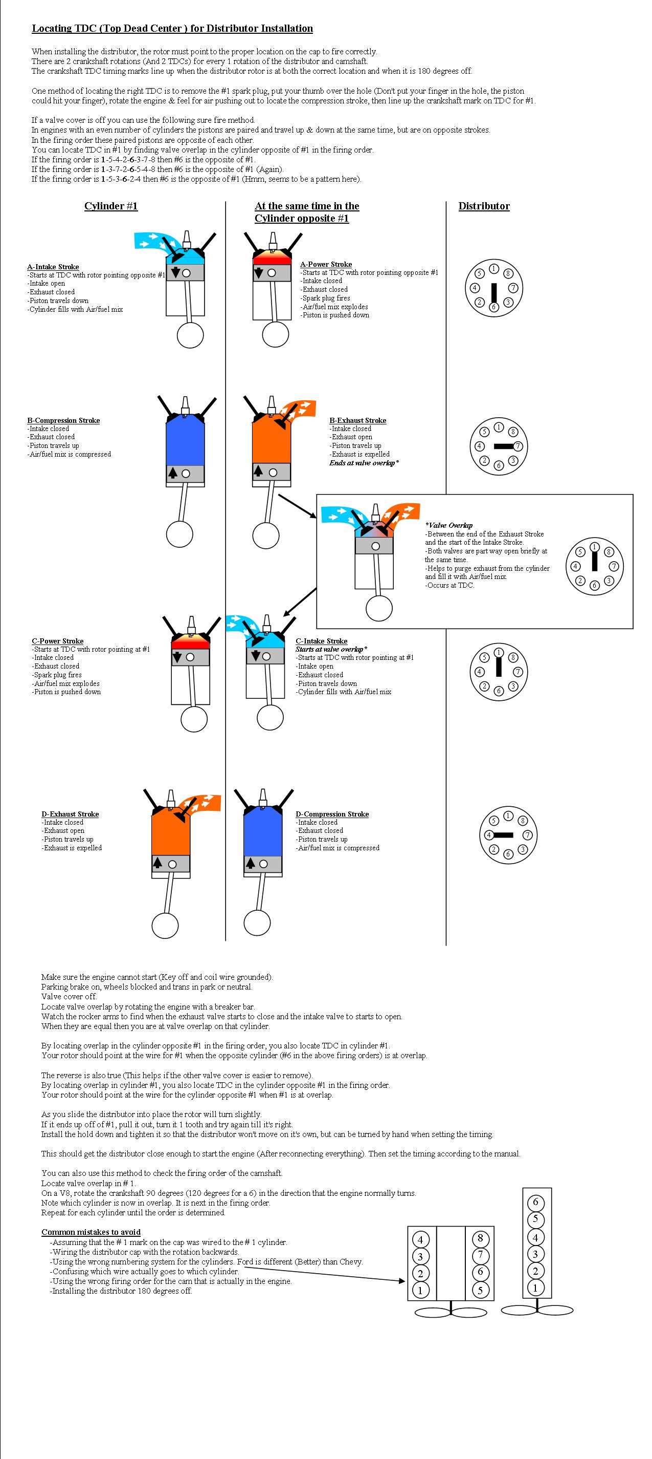
Service procedure for locating top dead center and installing the distributor, with four-stroke cycle figures and instructions.
Part of 1987-1991 Ford Bronco Service Procedures
This document is an illustrated service procedure explaining how to locate Top Dead Center (TDC) for cylinder #1 when installing a distributor. It explains that the crankshaft makes two rotations (two TDCs) per distributor/camshaft rotation, so crank timing marks align both at the correct rotor position and 180 degrees off. Two methods are described: feeling compression at the #1 spark plug hole, and a 'sure fire' valve-overlap method using paired cylinders, in Ford firing orders 1-5-4-2-6-3-7-8, 1-3-7-2-6-5-4-8, and 1-5-3-6-2-4, cylinder #6 is opposite #1. A four-row diagram sequence (A-D) shows cylinder #1 and its opposite cylinder through intake, compression, power, and exhaust strokes with matching distributor rotor positions, plus an inset explaining valve overlap. Step-by-step instructions cover safety (key off, coil wire grounded, brake set), rotating the engine with a breaker bar to find overlap, and adjusting the distributor one tooth at a time. It also explains how to verify camshaft firing order by rotating the crank 90° (V8) or 120° (six-cylinder) between overlaps. A 'Common mistakes to avoid' list warns about backwards cap wiring, wrong cylinder numbering (Ford vs. Chevy), and installing the distributor 180 degrees off. Ford V8 and inline-6 cylinder numbering diagrams are included.
Is this accurate? Sign in to help verify it.
Frequently asked questions
- How do I find TDC for cylinder #1 when installing a distributor?
- Either remove the #1 spark plug, put your thumb over the hole, rotate the engine and feel air pushing out to find the compression stroke, then align the crankshaft TDC mark; or, with a valve cover off, find valve overlap in the cylinder opposite #1 in the firing order, that puts #1 at TDC on its power stroke.
- Why do the crankshaft timing marks line up twice?
- There are 2 crankshaft rotations (and 2 TDCs) for every 1 rotation of the distributor and camshaft, so the marks line up both when the rotor is at the correct location and when it is 180 degrees off.
- Which cylinder is opposite #1 in Ford firing orders?
- Cylinder #6: in firing orders 1-5-4-2-6-3-7-8, 1-3-7-2-6-5-4-8, and 1-5-3-6-2-4, #6 is opposite #1.
- What is valve overlap?
- It occurs between the end of the exhaust stroke and the start of the intake stroke, when both valves are part way open briefly at the same time. It helps purge exhaust from the cylinder and fill it with air/fuel mix, and it occurs at TDC.
- What if the rotor ends up pointing off of #1 after installing the distributor?
- Pull the distributor out, turn it 1 tooth, and try again until it's right. Then install the hold down snug enough that the distributor won't move on its own but can still be turned by hand for timing.
- How can I check the camshaft firing order?
- Locate valve overlap in #1, then rotate the crankshaft 90 degrees (120 degrees for a 6-cylinder) in the normal direction; the cylinder now in overlap is next in the firing order. Repeat until the order is determined.






No comments yet.