SuperMotors SuperMotors SUPERMOTORS Search: try “orange Bronco on 35s”
Home/ Registry/ Ford/ Bronco/ 1987-1991/ “Eddie Bauer”/ Photo supermotors.net/registry/media/844685

Ford RFI Suppression Capacitor Install at Ignition Coil - 4.9L 5.0L 5.8L 7.5L MFI

Four labeled figures showing capacitor installation to ignition coil for 5.0L, 5.8L, 4.9L and 7.5L engines
Four labeled figures showing capacitor installation to ignition coil for 5.0L, 5.8L, 4.9L and 7.5L enginesOriginal file
Four labeled figures showing capacitor installation to ignition coil for 5.0L, 5.8L, 4.9L and 7.5L engines

Reference · 1987-1991 BroncoAll 95 service procedures
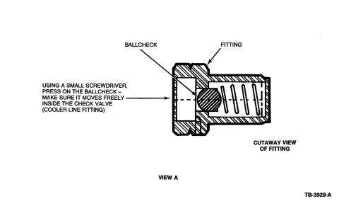
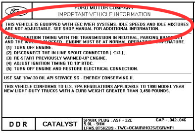
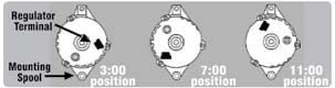
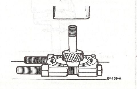
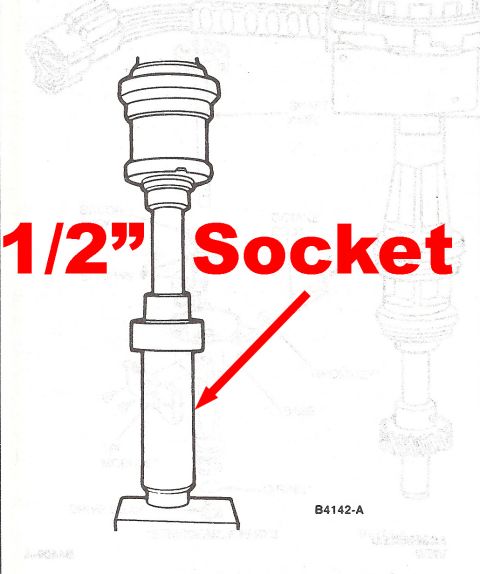
Ford E4OD Cooler Line Check Valve Ballcheck Inspection Diagram (TB-3929-A) Ford 1990 5.8L EEC IV EFI vehicle emission information label with ignition timing steps and spark plug spec Ford Alternator Clocking Diagram - 3:00, 7:00 & 11:00 Regulator Terminal Positions Ford Distributor Gear Removal Diagram - Press & Splitter Plate Setup (B4139-A) Ford Distributor Gear Installation Using 1/2" Socket - Service Diagram B4142-A Ford RFI Suppression Capacitor Install at Ignition Coil - 4.9L 5.0L 5.8L 7.5L MFI Locating TDC for Distributor Installation - Ford V8 & I6 Valve Overlap Method MSD distributor addendum on applying the camshaft and lifter lubricant to the drive gear 95service procedures1987-1991 Ford Bronco More reference 1973-1974 Ford Point-Type Ignition System Circuit Diagram - Coil & DistributorWiring diagram Ford Thermactor Air Bypass Valve Cutaway Diagram - Port IdentificationSchematic Ford 5.8L important engine information decal with 10° BTDC timing check and ASF-32C plugSpec plate Ford 5.0L V8 PCV Valve & Hose Routing Diagram - 9A474, 6B890, 6A664Exploded parts Ford 5.0L/5.8L Air Throttle Body Assembly Diagram - Canister Purge Ports & TPSManual page 1990 Bronco Major Standard Equipment sheet with interior features and functional specs by trimBrochure Borgeson Steering Intermediate Shaft Measurement Diagram - U-Joint Length B & CBlueprint Ford Thermactor Combination Valve Diagram - Air Bypass/Control Ports LabeledVacuum routing 1990 Ford Bronco Fuse Panel Diagram: Fuse Positions, Amps & Circuits (11-2)Fuse chart Ford V8 Intake Manifold Bolt Tightening Sequence Diagram - Stud LocationsTorque spec

Service figures illustrating capacitor-to-coil installation for various MFI engine and alternator configurations.

Part of 1987-1991 Ford Bronco Service Procedures

AI caption · Photo 351 of 1787

This document is a scanned Ford service illustration (figure code K20720-B) showing the installation of an RFI (radio frequency interference) suppression capacitor assembly onto the ignition coil for four different MFI engines. Four side-by-side line drawings depict the capacitor and its mounting/wiring at the coil assembly for: the 5.0L (MFI) engine, the 5.8L (MFI) engine, the 4.9L (MFI) engine equipped with a 75-amp alternator and manual transmission, and the 7.5L (MFI) engine. Each drawing includes numbered callouts (1 through 7 across the set) pointing to components such as the capacitor, coil, mounting bracket/hardware, and wiring connections, though the legend defining these numbers is not included on this page. A reader can learn where the suppression capacitor mounts relative to the ignition coil and how the routing differs among the 4.9L, 5.0L, 5.8L, and 7.5L multiport fuel injected engines. The scan contains no year range, torque values, or part numbers, and is likely one page of a larger service procedure.

Is this accurate? Sign in to help verify it.

Frequently asked questions

Which engines does this capacitor installation diagram cover?
It shows capacitor-to-ignition-coil installation for the 5.0L (MFI), 5.8L (MFI), 4.9L (MFI), and 7.5L (MFI) engines.
Are there special conditions for the 4.9L engine illustration?
Yes: the 4.9L (MFI) diagram applies specifically to engines with a 75 amp alternator and manual transmission.
Where does the RFI suppression capacitor mount?
According to the illustrations, the capacitor assembly is installed onto the ignition coil assembly on each engine.
Does the document identify the numbered callout parts?
No, the drawings use numbered callouts (1-7), but no legend or parts list defining them is visible on this page.


Comments

No comments yet.

More 1987-1991 Broncos