Home/
Registry/
Ford/
Taurus/
1996-1999/
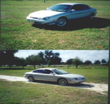
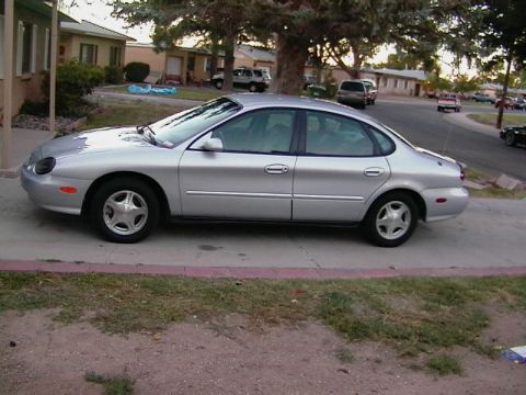
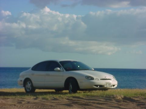
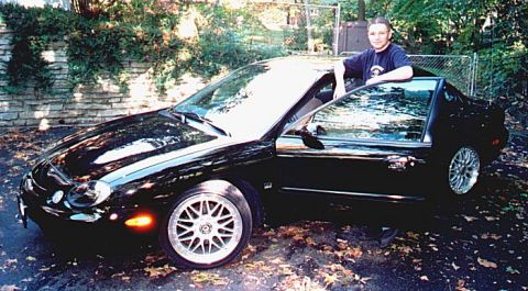
1997 Ford Taurus/
Photo
supermotors.net/registry/media/934056
Ford Taurus ICP Radio Wiring Diagram - Fuses, Wire Colors, GEM, EATC, RCU

Reference · 1996-1999 TaurusAll 33 wiring diagrams
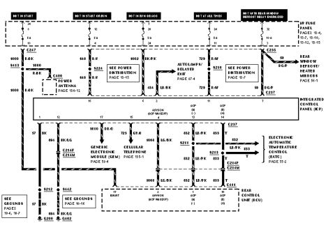
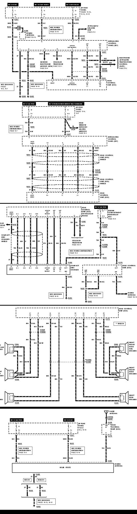
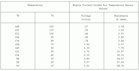
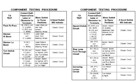
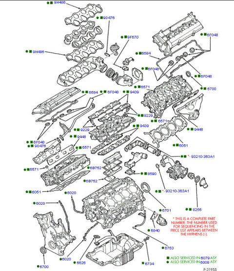
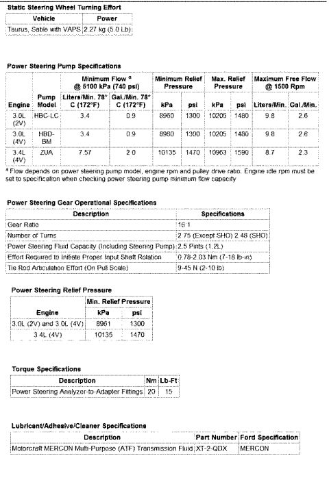
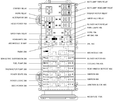

Electrical wiring diagram showing fuse panel feeds, integrated control panel, EATC and rear defrost circuits with color codes and connectors.
Part of 1996-1999 Ford Taurus Wiring Diagrams
This document is a factory-style wiring diagram for the Integrated Control Panel (ICP), the combined radio/climate control head unit, in a Ford Taurus/Sable-family vehicle. It shows five power feeds from the I/P fuse panel (pages 13-4 through 13-15): a 5A hot-in-start feed, a 5A hot-in-start-or-run feed (fuse 4), a 5A hot-in-run-or-acc feed (fuse 7), a 5A hot-at-all-times feed (fuse 24), and a 10A feed hot with the rear window defrost relay energized (fuse 32). Wire circuits are identified by number and color: 1000 R/BK (battery/accessory feed through splice S413, also feeding the power antenna via C400), 640 R/Y, 1002 BK/PK and 434 LB/BK (autolamps/delayed exit), 729 R/W, and 59 DG/P (rear window defrost/heated mirrors). Below the ICP, the diagram shows grounds 57 BK to G200 and 694 BK/LG to G402, plus data/audio lines: 1010 DB/O to the Generic Electronic Module (GEM), 723 GY/R to the cellular telephone, and ACP bus circuits 1068 LG/BK, 832 LB/PK, and 833 T linking the ICP to the Electronic Automatic Temperature Control (EATC) and the Rear Control Unit (RCU). Connector and splice IDs (C247, C235, C237, C214F/C214M, C411, S211, S213, S216, S224) and cross-reference page numbers are included.
Is this accurate? Sign in to help verify it.
Frequently asked questions
- Which fuses power the Integrated Control Panel (ICP)?
- Five I/P fuse panel feeds are shown: fuse 34 (5A, hot in start), fuse 4 (5A, hot in start or run), fuse 7 (5A, hot in run or acc), fuse 24 (5A, hot at all times), and fuse 32 (10A, hot with the rear window defrost relay energized).
- What wire carries constant battery power to the ICP?
- Circuit 729 R/W (red/white) from fuse 24 (5A, hot at all times) through splice S216, per Power Distribution page 13-7.
- Where are the ICP grounds located?
- Circuit 57 BK grounds through splice S212 to G200 (grounds pages 10-6, 10-7), and circuit 694 BK/LG passes through connector C214F/C214M and splice S442 to ground G402 (grounds page 10-16).
- What circuits connect the ICP to the EATC and Rear Control Unit?
- Circuit 1068 LG/BK (ACP wakeup / A5V50N), 832 LB/PK (ACP -), and 833 T (ACP +) run to the Electronic Automatic Temperature Control (page 55-2) and to the Rear Control Unit via C411 (RCU pins 2, 1, and 15).
- What wire connects the ICP to the GEM?
- Circuit 1010 DB/O from ICP pin 17 goes to the Generic Electronic Module (GEM), referenced on page 59-4.


No comments yet.