Home/
Registry/
Ford/
Taurus/
1996-1999/
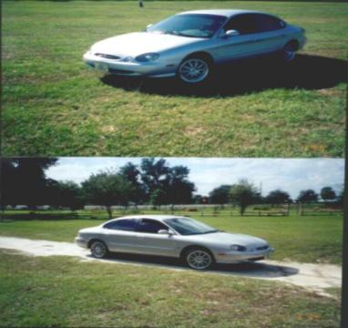
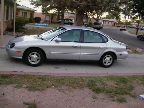
1997 Ford Taurus/
Photo
supermotors.net/registry/media/760569
Ford Taurus AX4N Transmission Range (TR) Sensor C107 Connector Pinout Diagram

Reference · 1996-1999 TaurusAll 33 wiring diagrams
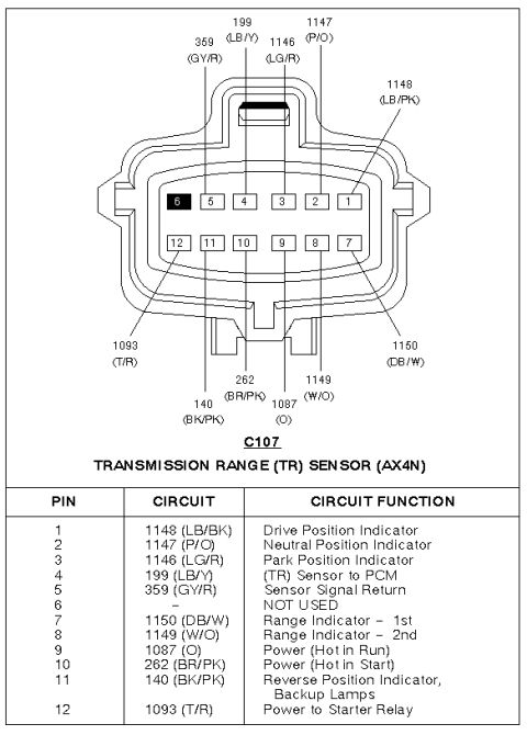

Wiring diagram of the AX4N transmission range (TR) sensor connector C107 with pins, color-coded circuits and functions.
Part of 1996-1999 Ford Taurus Wiring Diagrams
This document is a connector pinout reference for connector C107, the Transmission Range (TR) Sensor used with the AX4N automatic transaxle. It includes a face-view illustration of the 12-pin connector showing pin positions in two rows (pins 6-1 on top, 12-7 on bottom, with pin 6 shaded as not used) and callout labels identifying the circuit number and wire color for each pin. Below the diagram, a table lists each pin, its circuit number and wire color code, and its circuit function. Functions include the Drive, Neutral, and Park position indicators (circuits 1148, 1147, 1146), the TR sensor signal to the PCM (199 LB/Y), sensor signal return (359 GY/R), Range Indicator 1st and 2nd (1150 DB/W and 1149 W/O), power circuits hot in Run (1087 O) and hot in Start (262 BR/PK), the Reverse Position Indicator/Backup Lamps circuit (140 BK/PK), and power to the starter relay (1093 T/R). A reader can use this to identify wires at the TR sensor connector for diagnosis of no-start, backup lamp, gear indicator, or PCM range signal issues. Note that pin 1's color is shown as LB/PK in the diagram callout but LB/BK in the table.
Is this accurate? Sign in to help verify it.
Frequently asked questions
- What connector does this diagram cover?
- Connector C107, the Transmission Range (TR) Sensor connector for the AX4N transmission, a 12-pin connector.
- Which pin on the TR sensor connector supplies power to the starter relay?
- Pin 12, circuit 1093 (T/R: tan/red), is Power to Starter Relay.
- Which pin carries the TR sensor signal to the PCM?
- Pin 4, circuit 199 (LB/Y), is the (TR) Sensor to PCM circuit; pin 5, circuit 359 (GY/R), is the Sensor Signal Return.
- Which circuit controls the backup lamps?
- Pin 11, circuit 140 (BK/PK), is the Reverse Position Indicator / Backup Lamps circuit.
- Are any pins unused on connector C107?
- Yes, pin 6 is marked NOT USED and is shown shaded on the connector diagram.




No comments yet.