Home/
Registry/
Ford/
Mustang/
2005-2014/
“SHELBY GT500”/
Photo
supermotors.net/registry/media/942865
2007 Ford Mustang Supercharger & Fuel Rail Exploded Diagram - Torque Specs

Reference · 2005-2014 MustangAll 44 exploded parts diagrams

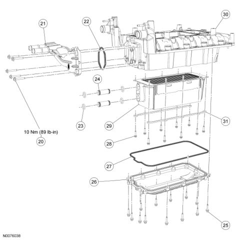
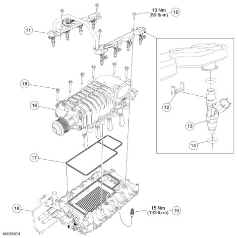
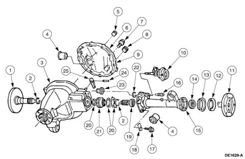
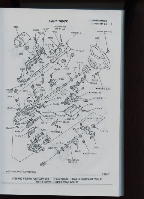









Exploded parts diagram of a supercharger assembly with fuel rail, injectors, gaskets and intake manifold, numbered with torque specs.
Part of 2005-2014 Ford Mustang Exploded Parts Diagrams
This is an exploded parts diagram (Ford illustration number N0085974) showing the disassembly/assembly of a supercharger and fuel rail installation on a V8 engine. Numbered callouts 10 through 19 identify components: the fuel rail retaining bolts (callout 10, torqued to 10 Nm / 89 lb-in), the fuel rail assembly with injectors (11), and an inset detail view showing an injector retaining clip (12), a fuel injector (13), and its O-ring seal (14). Below the fuel rail, the diagram shows the supercharger mounting bolts (15), the Roots-type supercharger assembly with its drive snout and pulley (16), the supercharger-to-lower-manifold gasket (17), a hose/tube assembly connected to the lower intake/intercooler manifold (18), and a sensor installed in the lower manifold (19) torqued to 15 Nm (133 lb-in). The diagram conveys the stacking order of the components: fuel rails and injectors on top, supercharger in the middle, gasket, and the lower intake manifold with integrated charge cooler at the bottom. A reader can learn the assembly sequence, relative component locations, and the two torque specifications shown. No part numbers, model year, or vehicle identification text appears in the illustration itself.
Is this accurate? Sign in to help verify it.
Frequently asked questions
- What is the torque spec for the fuel rail bolts in this diagram?
- Callout 10 shows the fuel rail bolts are torqued to 10 Nm (89 lb-in).
- What torque is specified for the sensor in the lower intake manifold?
- Callout 19 shows the sensor is torqued to 15 Nm (133 lb-in).
- What components are shown in the injector detail inset?
- The inset shows the injector retaining clip (12), the fuel injector (13), and its O-ring seal (14).
- Is there a gasket between the supercharger and the lower intake manifold?
- Yes, callout 17 shows a gasket that sits between the supercharger assembly (16) and the lower intake manifold.
- What is the Ford illustration number for this diagram?
- The illustration is marked N0085974.






No comments yet.