Home/
Registry/
Ford/
Mustang/
2005-2014/
“SHELBY GT500”/
Photo
supermotors.net/registry/media/942866
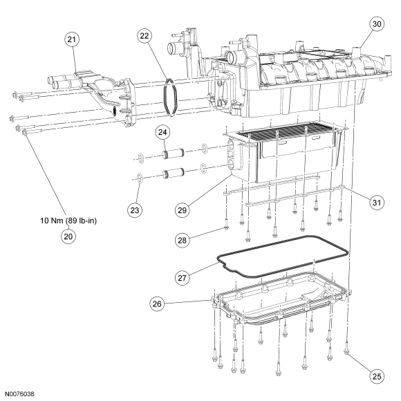
2007 Ford Mustang Supercharger/Intercooler Exploded Parts Diagram (N0076038)
Reference · 2005-2014 MustangAll 44 exploded parts diagrams
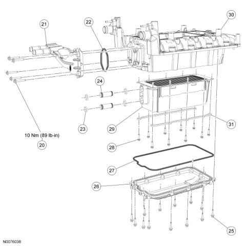
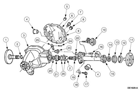
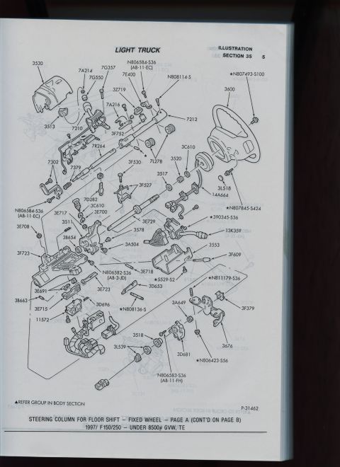
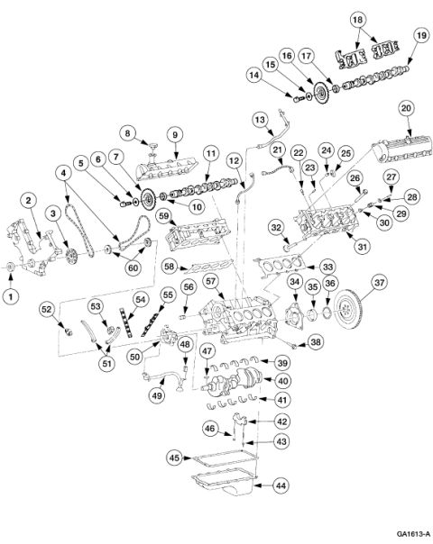
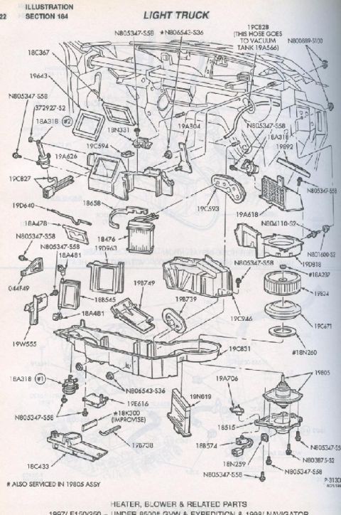
Exploded parts diagram of an intake manifold and intercooler assembly with gaskets, fasteners and lower pan, numbered callouts.
Part of 2005-2014 Ford Mustang Exploded Parts Diagrams
This document is an exploded-view parts illustration (figure reference N0076038) showing the disassembly/assembly relationship of what appears to be a supercharger or intake manifold assembly with an integrated intercooler. Numbered callouts 20 through 31 identify the components: an upper manifold/plenum assembly (30), a finned intercooler/cooler core (29) with associated long fasteners (31) and bolts (28), a perimeter gasket (27), a lower pan/housing (26) secured by numerous bolts (25), plus a left-side housing or shaft assembly (21), an O-ring gasket (22), small seals (23), and cylindrical bushings or tubes (24). The only torque specification given is 10 Nm (89 lb-in), tied to the fasteners at callout 20. No text legend accompanies the callouts in this scan, so component names are inferred from the drawing rather than stated; a companion page would normally list the part descriptions for each number. The file was uploaded to a 2007 Ford Mustang gallery with the filename SC3.gif, suggesting it depicts a supercharger assembly, but the document itself contains no year, model, or engine identification. Readers can learn the assembly order, gasket/seal locations, fastener positions, and the single visible torque value.
Is this accurate? Sign in to help verify it.
Frequently asked questions
- What torque specification is shown in this diagram?
- The only torque value shown is 10 Nm (89 lb-in), associated with the fasteners at callout 20.
- What callout numbers are included in this exploded view?
- Callouts 20 through 31, identifying fasteners, gaskets/seals, a cooler core assembly, an upper manifold/plenum, and a lower pan/housing.
- Does this diagram include a parts legend or part numbers?
- No. Only the numbered callouts, one torque value (10 Nm / 89 lb-in), and the figure reference N0076038 are shown; there is no legend listing part names or part numbers.
- What is the figure reference number of this illustration?
- N0076038, printed at the bottom left of the drawing.
No comments yet.