1990 Ford F-250 Center Console Gauge Panel Wiring Diagram - Voltmeter & Outlets
Reference · 1987-1991 F-250All 32 wiring diagrams
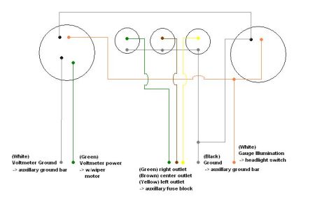



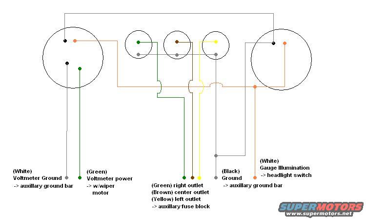
Wiring diagram showing voltmeter, accessory outlets and gauge illumination circuits with color-coded wires and labels.
Part of 1987-1991 Ford F-250 Wiring Diagrams
This document is a hand-drawn wiring diagram (created in a simple graphics program) for a custom center console gauge panel, uploaded to a 1990 Ford F-250 gallery. It depicts two large circular gauges (a voltmeter on the left and an illuminated gauge on the right) plus three smaller circular devices in the middle, which the legend identifies as right, center, and left power outlets. Wire colors and their destinations are labeled: a White wire is the Voltmeter Ground routed to an auxiliary ground bar; a Green wire supplies Voltmeter power tied in with the wiper motor circuit; Green, Brown, and Yellow wires feed the right, center, and left outlets respectively from an auxiliary fuse block; a Black wire is a Ground going to the auxiliary ground bar; and a second White wire provides Gauge Illumination fed from the headlight switch. The drawing uses colored lines matching each wire color to show routing between the gauges, outlets, and their power/ground sources. A reader can learn the wire color coding, power sources (wiper motor circuit, auxiliary fuse block, headlight switch), and grounding scheme (auxiliary ground bar) used in this owner-built console gauge and outlet panel. No fuse amperages, part numbers, or vehicle-specific year information appear in the drawing.
Is this accurate? Sign in to help verify it.
Frequently asked questions
- What color is the voltmeter ground wire and where does it connect?
- The voltmeter ground is a White wire that runs to the auxiliary ground bar.
- Where does the voltmeter get its power?
- A Green wire supplies voltmeter power, tied in with the wiper motor circuit.
- What wire colors feed the three power outlets?
- Green feeds the right outlet, Brown the center outlet, and Yellow the left outlet; all come from the auxiliary fuse block.
- How is the gauge illumination wired?
- Gauge illumination uses a White wire connected to the headlight switch.
- Where is the panel's main ground connected?
- A Black ground wire runs to the auxiliary ground bar.

No comments yet.