Home/
Registry/
Chevrolet/
Corvette/
1968-1982/
“stingray76”/
Photo
supermotors.net/registry/media/996284
Driveshaft U-Joint Angle Diagram - Compensating vs Broken Back W Configuration

Reference · 1968-1982 CorvetteAll 4 schematics
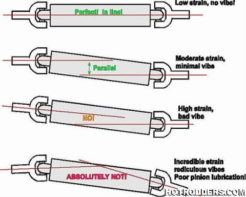
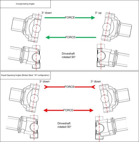
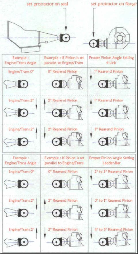
Technical schematic comparing compensating U-joint angles and equal-opposing (broken-back) angles with force arrows on a rotating driveshaft.
Part of 1968-1982 Chevrolet Corvette Schematics
This document is a technical schematic illustrating two common driveshaft universal joint (U-joint) working-angle configurations. The top panel, labeled "Compensating Angles," shows a driveshaft with one U-joint angled 3° down and the opposite U-joint angled 3° up (parallel yokes), with green FORCE arrows pointing in the same directions at both ends, plus side views showing the driveshaft rotated 90°. The bottom panel, labeled "Equal Opposing Angles (Broken Back: 'W' configuration)," shows both U-joints angled 3° down, with red FORCE arrows indicating forces that oppose or converge, again accompanied by views of the driveshaft rotated 90°. Red dashed centerlines through each yoke illustrate the angular relationship of the joint axes in each layout. A reader can learn how the two acceptable driveshaft geometry setups differ: in the compensating (parallel) arrangement the equal-and-opposite 3° angles cancel each other's velocity fluctuations with forces acting in the same direction, while in the broken-back "W" arrangement equal opposing 3° angles also cancel but produce opposing force directions. The drawings show yoke and U-joint cross details in both plan and 90°-rotated orientations, making this a general drivetrain geometry reference rather than a vehicle-specific document.
Is this accurate? Sign in to help verify it.
Frequently asked questions
- What two driveshaft angle configurations does this diagram show?
- It shows "Compensating Angles" (one U-joint 3° down, the other 3° up) and "Equal Opposing Angles," described as the Broken Back or "W" configuration (both U-joints 3° down).
- What angle values are used in the examples?
- Both configurations use 3° joint angles: 3° down and 3° up for the compensating layout, and 3° down at both ends for the broken-back "W" layout.
- How do the force directions differ between the two configurations?
- In the compensating-angle layout, the FORCE arrows at both ends point in the same direction, while in the equal opposing angle (broken back "W") layout, the FORCE arrows oppose each other.
- What do the secondary views in each panel represent?
- They show the same driveshaft and U-joints rotated 90°, illustrating the joint alignment from a second viewing plane.
No comments yet.