Home/
Registry/
Chevrolet/
Corvette/
1968-1982/
“stingray76”/
Photo
supermotors.net/registry/media/1018245
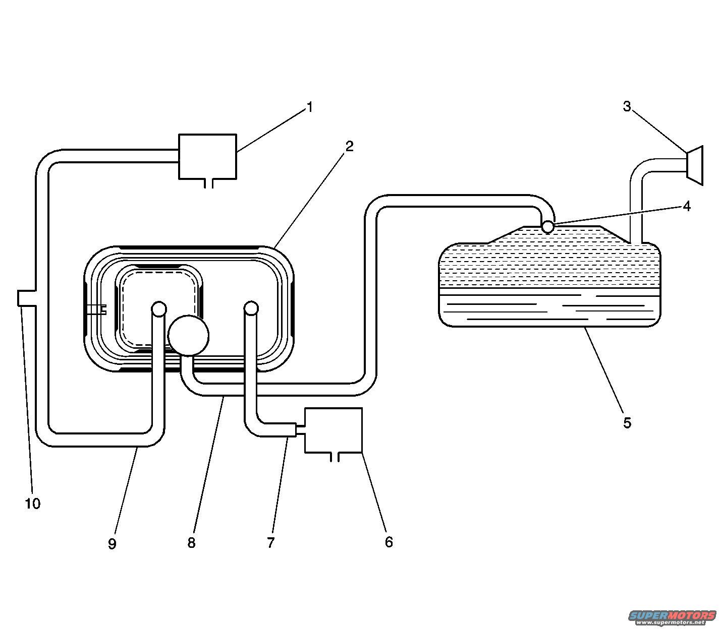
GM 8.1L EVAP System Hose Routing Diagram - Canister, Tank & Vent Lines
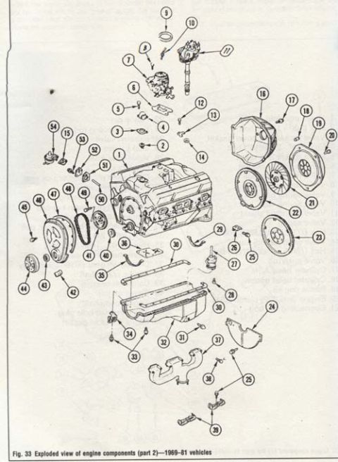
Reference · 1968-1982 CorvetteAll 34 exploded parts diagrams
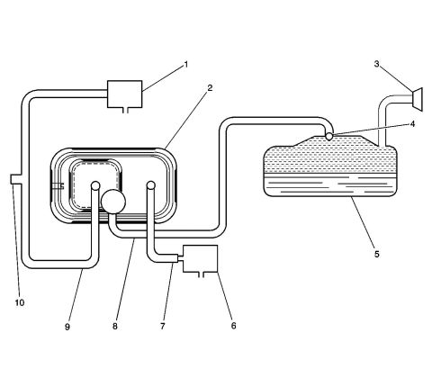
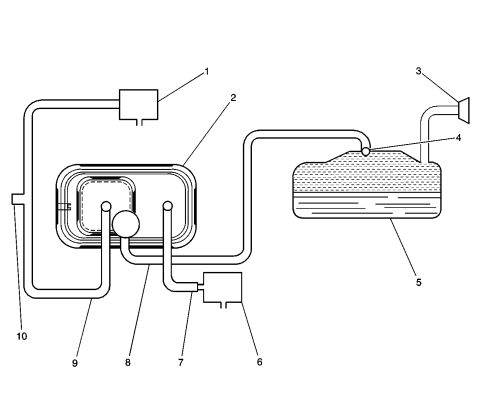
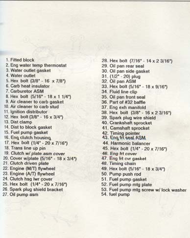
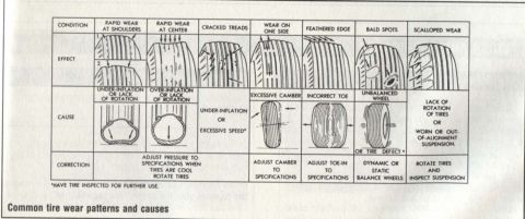
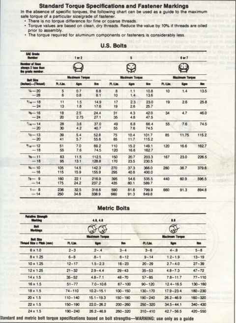
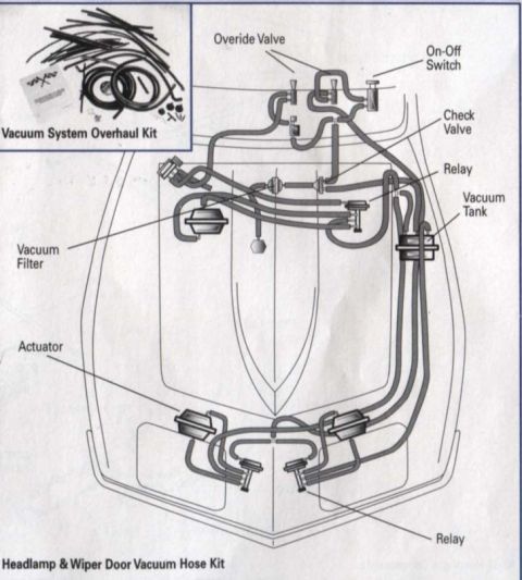
Component diagram of a fuel tank and vapor-canister system with numbered callouts identifying lines, valves and the filler.
Part of 1968-1982 Chevrolet Corvette Exploded Parts Diagrams
This document is an unlabeled line-art routing diagram of an evaporative emission (EVAP) system, filed by the uploader as the '8.1L EVAP route.' It contains no written legend or text other than ten numbered callouts (1-10) pointing to system components and hose runs. The diagram shows a fuel tank (callout 5) partly filled with fuel, with a rollover/vent fitting on top (4) and a fill/vent pipe with a flared opening (3). Vapor lines route from the tank to a large EVAP canister assembly (2). Two small rectangular components, likely solenoid valves (1 and 6), are connected into the hose network, with individual hoses and tubes identified by callouts 7, 8, and 9, and an open vent fitting at callout 10. A reader can learn the general plumbing arrangement of the EVAP system, how the tank, canister, vent, and control valves are interconnected, but because the source page carries no legend, exact component names, part numbers, years, or model applicability cannot be confirmed from this image alone. The diagram would typically accompany a service-manual legend page identifying each numbered item.
Is this accurate? Sign in to help verify it.
Frequently asked questions
- What does this diagram show?
- It is a routing diagram of an evaporative emission (EVAP) system, showing a fuel tank, a canister assembly, vent/fill fittings, two small valve components, and the hoses connecting them, identified by callouts 1 through 10.
- Does the diagram include a legend naming each numbered component?
- No. Only the callout numbers 1-10 are printed on the page; no legend, labels, or part names are visible.
- How is the fuel tank connected in this diagram?
- The tank (callout 5) has a fitting on top (callout 4) and a flared fill/vent pipe (callout 3); a vapor hose runs from the tank area to the canister assembly (callout 2).
- How many hoses/lines are individually called out?
- Three hose/line callouts are shown (7, 8, and 9), plus an open vent fitting at callout 10.
No comments yet.