Home/
Registry/
Ford/
Bronco/
1980–1986/
“That dirty old truck”/
'90-96 Fuel Pump System
supermotors.net/registry/2742/12737
Album section
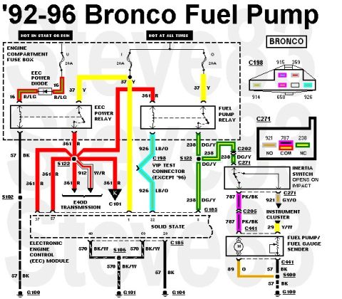
'90-96 Fuel Pump System
From 1983 Ford Bronco “That dirty old truck” — documented by Steve83.
81 photos
![1983 Ford Bronco - '84-96 fullsize Ford truck EFI Fuel Flow IF THE IMAGE IS TOO SMALL, click it. [url=https://www.supermotors.net/registry/media/919580] https…](https://www.supermotors.net/thumb/950180-480.jpg)
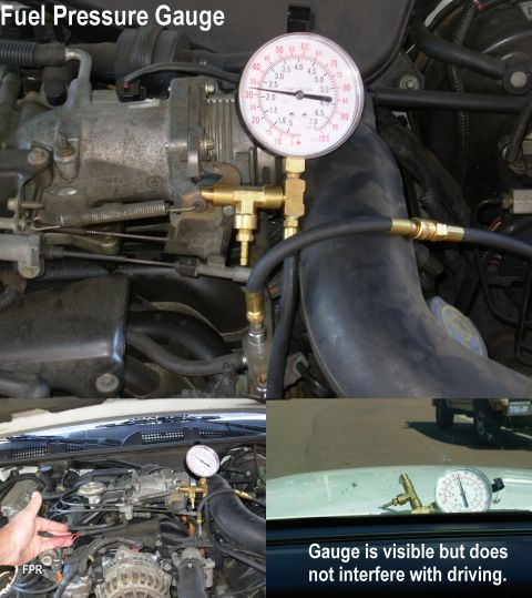
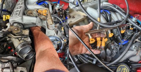
![1983 Ford Bronco - V8 Fuel Pressure Port, Distributor, IAC, & Vacuum Tree (top R) [url=http://www.supermotors.net/registry/media/825934] http://www.supermotor…](https://www.supermotors.net/thumb/148980-480.jpg)

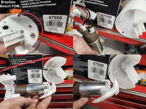
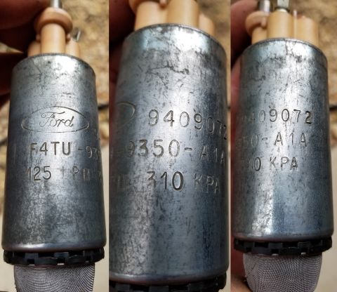
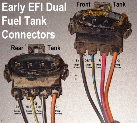
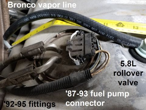
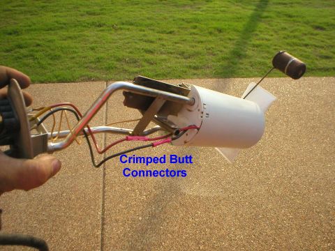
![1983 Ford Bronco - Fuel Pump Connector comparison [url=https://www.supermotors.net/registry/media/1126824] https://www.supermotors.net/getfile/1126824/thumbna…](https://www.supermotors.net/thumb/1164369-480.jpg)
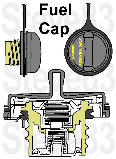
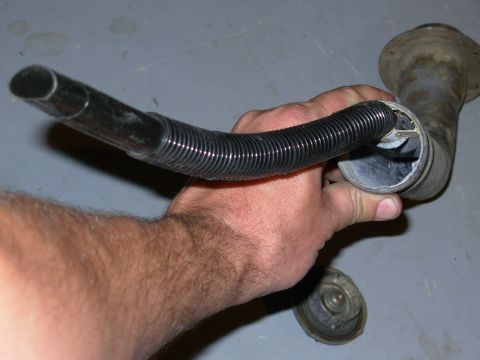
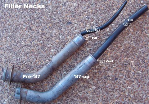
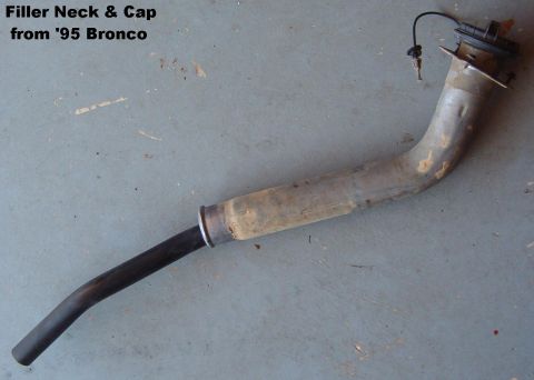
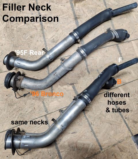
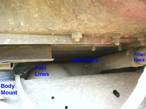
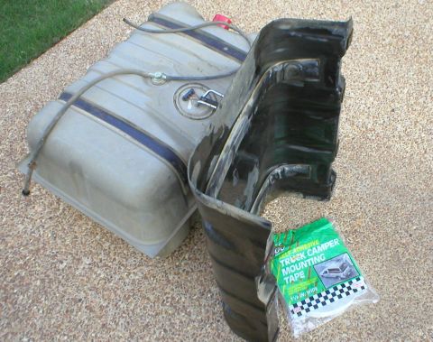
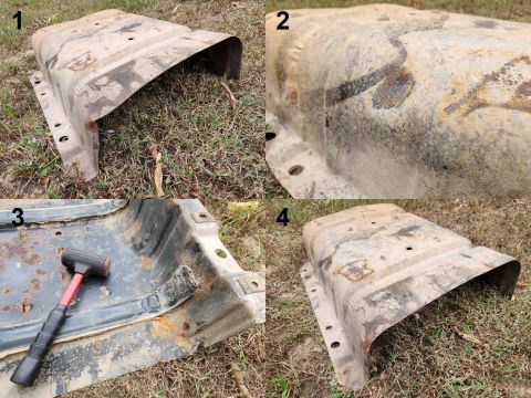
![1983 Ford Bronco - '87-96 Filler Neck See also: [url=https://www.supermotors.net/registry/media/1150549] https://www.supermotors.net/getfile/1150549/thumbnail…](https://www.supermotors.net/thumb/767952-480.jpg)
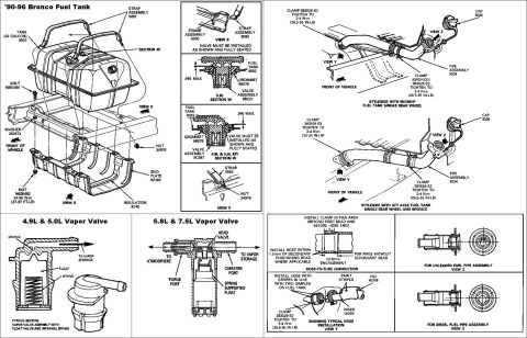
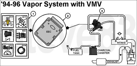
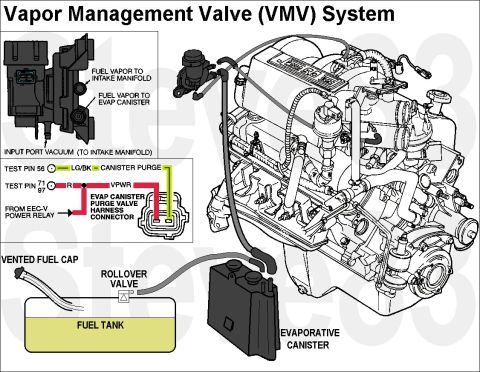
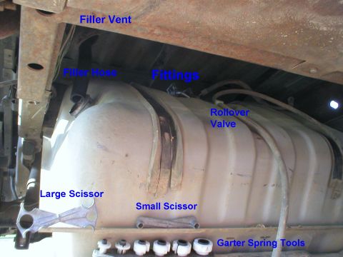
![1983 Ford Bronco - Vapor Valves The smaller valve ([url=https://www.amazon.com/dp/B008D33ZF8/]E7DZ9B593A ) uses a thicker (smaller I.D.) grommet (E3EC9B076AA…](https://www.supermotors.net/thumb/767956-480.jpg)
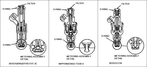
![1983 Ford Bronco - Fuel Injector PNs & Specs IF THE IMAGE IS TOO SMALL, click it. See also: [url=https://www.supermotors.net/registry/media/724074_1] https://…](https://www.supermotors.net/thumb/258009-480.jpg)
![1983 Ford Bronco - Inertia Switch old style [url=https://www.supermotors.net/registry/media/862997] https://www.supermotors.net/getfile/862997/thumbnail/inert…](https://www.supermotors.net/thumb/178339-480.jpg)
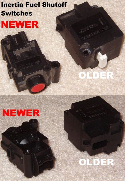
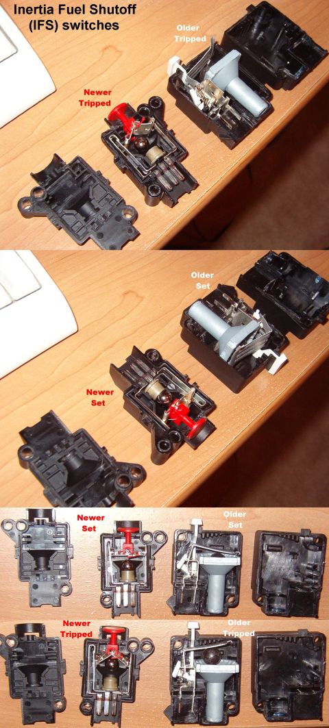
![1983 Ford Bronco - Inertia Switch new style [url=http://www.supermotors.net/registry/media/262703] http://www.supermotors.net/getfile/262703/thumbnail/inertia…](https://www.supermotors.net/thumb/178340-480.jpg)
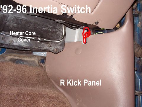
![1983 Ford Bronco - 92-93 Inertia Fuel Shutoff Switch Reset Indicator [url=http://www.supermotors.net/vehicles/registry/media/178340] http://www.supermotors.ne…](https://www.supermotors.net/thumb/1096359-480.jpg)