Home/
Registry/
Ford/
Bronco/
1980-1986/
“That dirty old truck”/
Photo
supermotors.net/registry/media/1172270
1992-96 Ford Bronco Fuel Pump Wiring Diagram - Relay, Inertia Switch, EEC

Reference · 1980-1986 BroncoAll 92 wiring diagrams
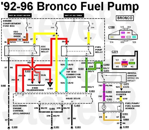






'92-96 Bronco Fuel Pump & Level Wiring
IF THE IMAGE IS TOO SMALL, click it.
Tank connectors & pinouts are shown here:
G100 is on the back of the core support directly above the body mount.
'90-91 similar
'87-89 ONLY has the high-pressure pump (mounted inside the frame rail under the driver's seat) wired between the IFS (XF3Z9341AA) & tank; those tank pumps are low-pressure, plumbed to the SFR near the frame pump.
See also: .
.  .
.  .
.  .
.  .
.  .
. 
Part of 1980-1986 Ford Bronco Wiring Diagrams
This is a wiring diagram for the fuel pump circuit on 1992-1996 Ford Broncos. It shows power distribution from the engine compartment fuse box: fuse U (20A, hot in start or run) and fuses I and O (20A each, hot at all times) feeding the EEC power relay and fuel pump relay via yellow (37 Y) wires, with an EEC power diode on circuit 16 R/LG. The diagram traces circuit 361 (red) through splice S122 to the relays, circuit 926 (yellow / light blue-orange) to the E4OD transmission connector C101 and the VIP test connector C198 (except 1996 models), and circuit 238 (dark green/yellow) through connectors C202 and C271 to the inertia switch, which opens on impact. From the inertia switch, circuit 787 (pink/black) runs through C205 and C441 to the fuel pump/fuel gauge sender, with circuit 921 (dark green/yellow) feeding the instrument cluster (29 Y/W output). Ground paths use black (57) and black/white (570) wires through splices S106 and S400 to grounds G100, G101, G104, and G185. Connector pinouts for C198 (pins 915, 359, 914, 658, 926) and C271 (921/787/238: NO/COM/NC) are illustrated. The EEC module pins 1, 22, 60, 40, and 20 are labeled.
This document covers 1992-1996, which may differ from this 1983 Ford Bronco.
Is this accurate? Sign in to help verify it.
Frequently asked questions
- What fuses power the fuel pump circuit on a 1992-1996 Ford Bronco?
- Three 20A fuses in the engine compartment fuse box: fuse U (hot in start or run) and fuses I and O (hot at all times), feeding the EEC power relay and fuel pump relay via 37 Y wires.
- What wire color goes from the fuel pump relay to the inertia switch?
- Circuit 238 DG/Y (dark green/yellow), passing through connectors C202 and C271 to the inertia switch.
- What wire feeds the fuel pump from the inertia switch?
- Circuit 787 PK/BK (pink/black), which runs through connectors C205 and C441 to the fuel pump/fuel gauge sender.
- What does the inertia switch do in this circuit?
- The diagram notes the inertia switch 'opens on impact,' interrupting the 238 DG/Y feed to the 787 PK/BK fuel pump wire at connector C271 (NO/COM/NC terminals 921/787/238).
- Which connector is the VIP test connector and does it apply to all years?
- C198 is the VIP test connector, connected by wire 926 LB/O; the diagram states it applies 'except '96'.






No comments yet.