Home/
Registry/
Ford/
Bronco/
1978-1979/
1978 Ford Bronco/
Photo
supermotors.net/registry/media/646054
1978 Ford 400 V8 Vacuum Diagram - Pickup & Bronco California Auto Trans
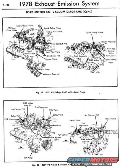
1978 Ford exhaust-emission vacuum diagrams for the 400 V8 pickup/Bronco with automatic trans, showing EGR valve, spark delay valves, PVS, air pump and vacuum reservoir routing.
This is page 3-92 from a 1978 Exhaust Emission System reference (Ford Motor Co. Vacuum Diagrams, continued), showing two labeled vacuum-routing illustrations for the 400 cubic-inch V8. Figure 39 covers the 400" V8 Pickup, California emissions, with automatic transmission; it shows two engine views with callouts identifying the EGR vacuum control valve, multiple spark delay valves, PCV valve, vacuum solenoid throttle kicker, cold lockout PVS, vacuum vent valve, distributor PVS, bypass valve, air pump, vacuum reservoir, vacuum amplifier, fuel separator, EGR valve, and air-cleaner connections. Figure 40 covers the 400" V8 Pickup & Bronco, California, with automatic transmission; its callouts include the EGR valve with back-pressure (B.P.), air cleaner TVS, fuel separator, PCV valve, delay valves, EGR vacuum control valve, restrictor, TVS, AIR by-pass valve, and AIR pump. Vacuum hose lengths and colors (e.g., 14" blue, 10" yellow, various black, red, and green hoses) are printed along the hose routings, though many are only partially legible in this scan. A reader can use this page to identify emission components and verify factory vacuum hose routing on a California-emissions 1978 Ford 400 V8 truck or Bronco with automatic transmission.
Is this accurate? Sign in to help verify it.
Frequently asked questions
- What vehicles do these vacuum diagrams apply to?
- Fig. 39 applies to the 400" V8 Pickup, California emissions, with automatic transmission. Fig. 40 applies to the 400" V8 Pickup & Bronco, California, with automatic transmission, per the 1978 Exhaust Emission System section.
- What emission components are labeled on the 1978 400 V8 California vacuum diagram?
- Labeled components include the EGR vacuum control valve, spark delay valves, PCV valve, vacuum solenoid throttle kicker, cold lockout PVS, vacuum vent valve, distributor PVS, bypass valve, air pump, vacuum reservoir, vacuum amplifier, fuel separator, and EGR valve.
- Does the 1978 Bronco 400 V8 California setup use an EGR valve with back pressure?
- Yes. Fig. 40 for the 400" V8 Pickup & Bronco (Calif., auto. trans.) labels an 'EGR Valve with B.P.' along with an EGR Vacuum Control Valve.
- Does this diagram show an air injection (AIR) system?
- Yes. Fig. 40 shows an AIR Pump and an AIR By-pass Valve; Fig. 39 also shows an Air Pump and Bypass Valve.
- Are vacuum hose colors and lengths indicated?
- Yes, hose lengths and colors are printed along the routings (e.g., 14" blue, 10" yellow, 18" black, red and green hoses), though many are only partially legible in this scan.
Comments
More from this build






No comments yet.