Home/
Registry/
Ford/
Bronco/
1978-1979/
1978 Ford Bronco/
Photo
supermotors.net/registry/media/646055
1978 Ford 400 V8 Pickup Vacuum Diagram - Federal Auto Trans (Figs 37-38)
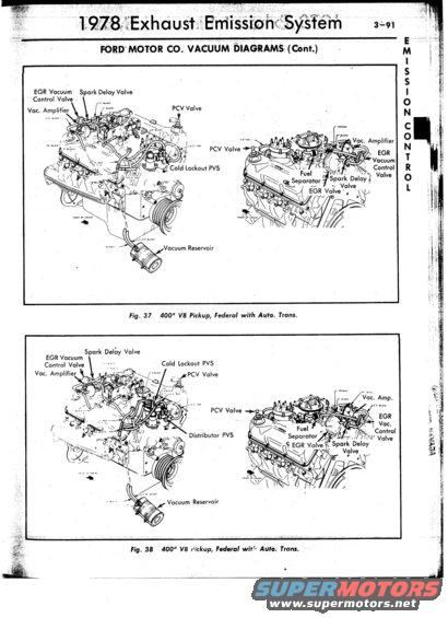
1978 Ford emission-control vacuum routing diagrams for the 400 V8 pickup (Federal, automatic): EGR valve, EGR vacuum control valve, spark delay valve, PCV valve and vacuum amplifier hose paths.
This page (3-91) is from a 1978 Exhaust Emission System reference section titled 'Ford Motor Co. Vacuum Diagrams (Cont.)', with an 'Emission Control' tab on the margin. It contains two vacuum hose routing illustrations, Fig. 37 and Fig. 38, both labeled '400" V8 Pickup, Federal with Auto. Trans.', covering the Ford 400 cubic inch V8 in Federal (49-state) emissions trucks with automatic transmission. Each figure shows two perspective engine drawings (front-left and rear-right views) with callouts identifying emission components: EGR Vacuum Control Valve, Vacuum Amplifier, Spark Delay Valve, PCV Valve, Cold Lockout PVS, Distributor PVS (Fig. 38), Fuel Separator, EGR Valve, and Vacuum Reservoir. Small annotations along the hoses give hose lengths and colors (e.g., 3.5 BLACK, 5" ORANGE, 13.5 RED, 6.5" TAN, 26" BLACK), allowing a reader to identify and route each vacuum line correctly. A reader can use this page to restore or verify factory vacuum hose routing and component placement on a 1978 Ford 400 V8 pickup engine with automatic transmission under Federal emissions calibration.
Is this accurate? Sign in to help verify it.
Frequently asked questions
- What engine and configuration do these vacuum diagrams cover?
- Both Fig. 37 and Fig. 38 are labeled '400" V8 Pickup, Federal with Auto. Trans.', the Ford 400 cubic inch V8 in Federal-emissions pickups with automatic transmission, from the 1978 Exhaust Emission System section.
- What emission components are identified in the diagrams?
- Callouts identify the EGR Vacuum Control Valve, Vacuum Amplifier, Spark Delay Valve, PCV Valve, Cold Lockout PVS, Distributor PVS (Fig. 38), Fuel Separator, EGR Valve, and Vacuum Reservoir.
- Do the diagrams show vacuum hose colors and lengths?
- Yes: small annotations along the hoses list lengths and colors such as 3.5 BLACK, 5" ORANGE, 13.5 RED, 6.5" TAN, 9" BLACK, and 26" BLACK, though many are only partially legible in this scan.
- Where is the Vacuum Reservoir located in these diagrams?
- In both Fig. 37 and Fig. 38 the Vacuum Reservoir is shown as a canister connected by a long black hose (marked 26" BLACK) routed down from the engine.
- Are these diagrams for California or Federal emissions vehicles?
- Both figures are explicitly labeled 'Federal', meaning 49-state (non-California) emissions calibration.
Comments
More from this build






No comments yet.