Home/
Registry/
Ford/
Bronco/
1980-1986/
1986 Ford Bronco/
Photo
supermotors.net/registry/media/1051309
1986 Ford Bronco Vacuum Hose Routing Diagram - EGR, Purge, Dual Tank Lines
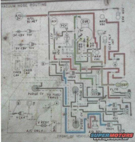
Vacuum hose routing label showing color-coded lines between EGR, PCV, carbon canisters, and other emissions components.
This document is a scanned, hand-annotated vacuum hose routing diagram titled "VACUUM HOSE ROUTING." It shows the layout of vacuum lines and emissions-control components as viewed from above, with "FRONT OF VEHICLE" marked at the bottom. Hand-written labels identify components including the A/CL DV (air cleaner duct/valve), A/CL BI MET (bi-metal sensor), ACV, PCV, EGR valve, manifold vacuum (MAN VAC) taps, exhaust heat control valve (EXH HCV), heat valve (HEAT VLV INT), TK (thermactor check), two SV CBV TVV assemblies, two carburetor canisters (CARB CAN), multiple purge control valves (PURGE CV) with a line noted "TO FUEL TANKS," distributor (DIST) vacuum connection, filter (FLTR), VCV, VDV, VRDV, IVV, LCV, HICV, VCKV, TVS, SOL V, vacuum restrictor (V REST), and AIR BPV (air bypass valve). An inset box labeled "A/C ONLY" shows additional routing (VCKV, V REST, SOL V, TK) used on air-conditioned vehicles, with connection points A and B tying the inset into the main diagram. Hoses are traced in colors (red, green, blue, tan/yellow, gray) to help distinguish circuits. A reader can use this diagram to route or verify vacuum hoses on the emissions and vacuum control system of this Ford truck, including dual fuel tank purge plumbing.
Is this accurate? Sign in to help verify it.
Frequently asked questions
- What does this diagram show?
- It is a vacuum hose routing diagram showing how vacuum lines connect emissions components such as the EGR valve, PCV, purge control valves, carbon canisters (CARB CAN), distributor, AIR BPV, and various vacuum valves (VCV, VDV, VRDV, TVV, TVS).
- Does the diagram cover dual fuel tanks?
- Yes. A purge control valve (PURGE CV) line is labeled "TO FUEL TANKS," and multiple purge CV callouts appear, indicating routing for more than one tank.
- Is there separate routing for A/C-equipped vehicles?
- Yes. An inset box labeled "A/C ONLY" shows additional components (VCKV, V REST, SOL V, TK) with connection points A and B tying into the main diagram.
- How is the diagram oriented?
- The bottom of the diagram is marked "FRONT OF VEHICLE," so the layout is viewed as if looking down at the engine bay from above.
- Where does the distributor vacuum come from in this diagram?
- The distributor (DIST) is shown on the right side connected through a filter (FLTR) and vacuum control valves (VCV) into the vacuum circuit.
Comments
More from this build






No comments yet.