Home/
Registry/
Ford/
Bronco/
1980-1986/
“Wild Cayuse”/
Photo
supermotors.net/registry/media/1108415
1985 Ford Bronco Vacuum Hose Routing Diagram - EGR, TAB/TAD Solenoids, Canister

Reference · 1980-1986 BroncoAll 13 vacuum routing diagrams
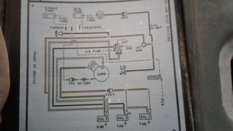
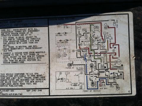
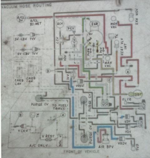
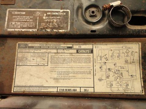
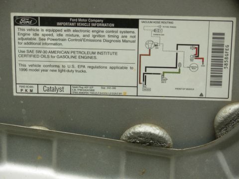
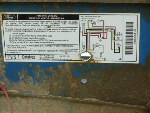
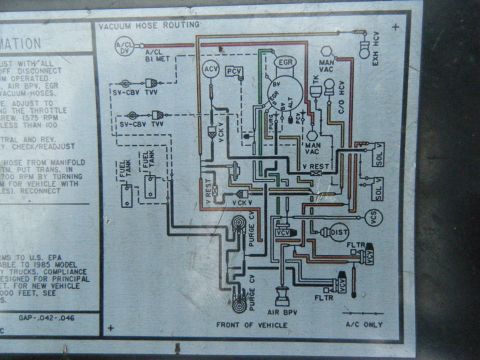
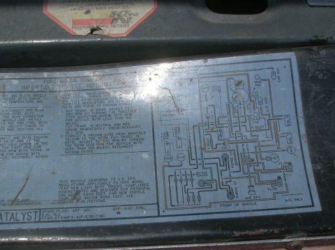
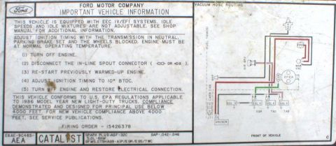
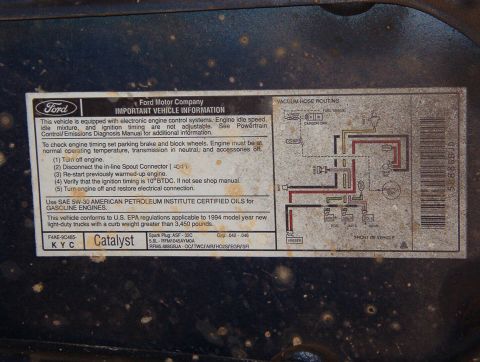
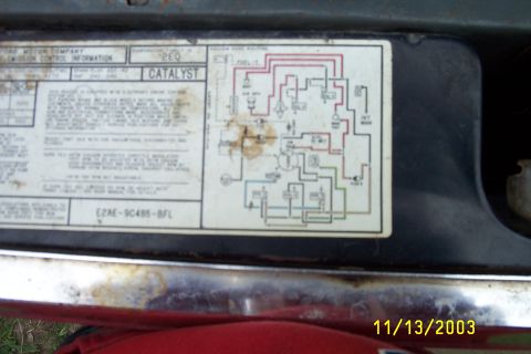
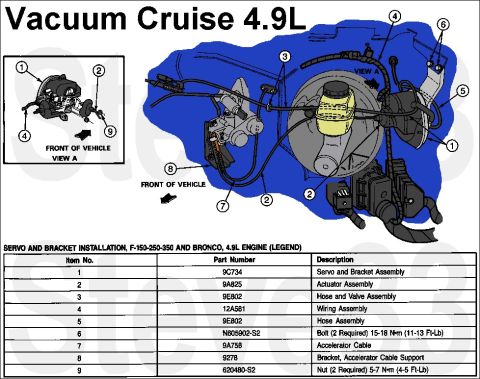







Vehicle emission control vacuum hose routing diagram showing carburetor, air pump, catalyst and EGR/TAD/TAB solenoid valve plumbing.
Part of 1980-1986 Ford Bronco Vacuum Routing Diagrams
This document is a photograph of a factory underhood vacuum hose routing diagram (emissions decal/reference sheet) for a carbureted Ford vehicle, uploaded to the gallery of a 1985 Ford Bronco. The schematic is oriented with 'FRONT OF VEHICLE' marked on the left and is titled 'VACUUM HOSE ROUTING' along the right edge. It depicts vacuum line routing for both single-tank and dual-tank fuel configurations, with fuel tank vapor lines feeding carbon canister(s). Components shown include the MAP sensor, air cleaner duct/diverter valve (A/CL DV), vacuum retard delay valve (VRDV), air cleaner bi-metal sensor (A/CL BI MET), air pump and air control valve (ACV) routing to the catalyst (CAT) and engine (ENG), intake manifold (INT MAN), carburetor with EGR valve, P/D motor, TVV and SV-CBV valves, vacuum check valve (V CK V), CPRV, PCV, and three solenoid valves (SOL V) that control the EGR, TAD (thermactor air diverter), and TAB (thermactor air bypass) functions. Hoses are drawn with different line styles and colors (orange, green, black, pink) to distinguish circuits. A reader can use this diagram to identify how each vacuum hose should be routed between emissions components when reassembling or diagnosing the vacuum system.
Is this accurate? Sign in to help verify it.
Frequently asked questions
- What does this diagram show?
- It is a 'Vacuum Hose Routing' diagram showing how vacuum hoses connect between emissions components such as the carbon canister(s), carburetor, EGR valve, air pump/ACV, intake manifold, and solenoid valves.
- Does the diagram cover both single and dual fuel tank setups?
- Yes. It shows separate 'SINGLE TANK' and 'DUAL TANK' fuel tank symbols, each routed to the carbon canister(s).
- Which solenoid valves are shown at the bottom of the diagram?
- Three 'SOL V' solenoid valves are shown, labeled for EGR, TAD, and TAB.
- What air injection (thermactor) components are shown?
- The diagram shows the AIR PUMP connected to an ACV (air control valve) with outputs marked CAT (catalyst) and ENG (engine), plus a vacuum check valve (V CK V).
- How is the diagram oriented?
- The left edge is marked 'FRONT OF VEHICLE', so the layout corresponds to the engine bay as viewed from above with the front of the vehicle to the left.






No comments yet.