Home/
Registry/
Ford/
Bronco/
1992-1996/
1993 Ford Bronco/
Photo
supermotors.net/registry/media/1064019
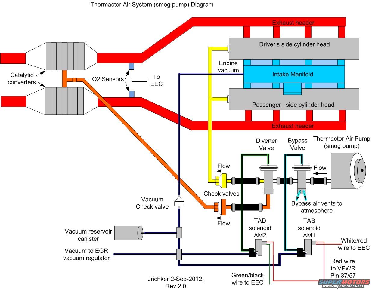
Ford Thermactor Air System (Smog Pump) Diagram - Vacuum & Wiring Routing
Reference · 1992-1996 BroncoAll 40 vacuum routing diagrams
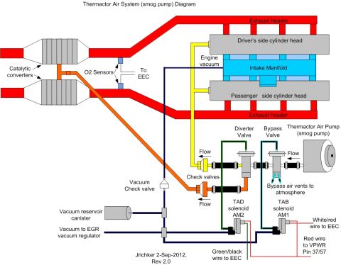

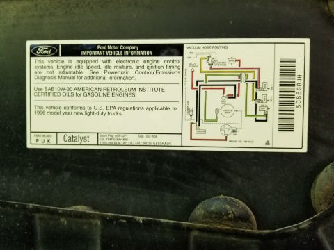
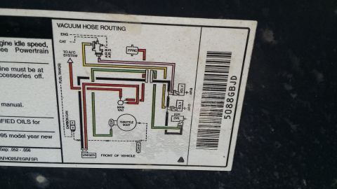
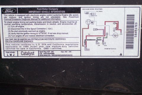
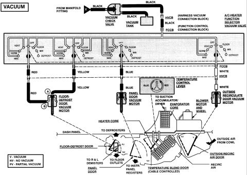
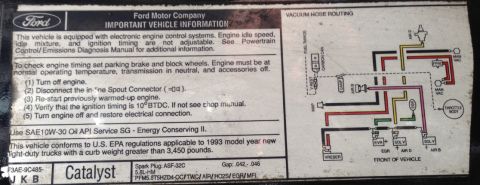
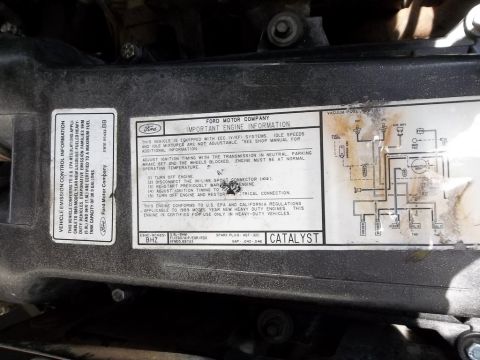








Thermactor air injection (smog pump) system diagram showing air pump, diverter and bypass valves, TAD (AM2) and TAB (AM1) vacuum solenoids, check valves, and EEC vacuum/electrical routing to both cylinder heads and catalysts.
Part of 1992-1996 Ford Bronco Vacuum Routing Diagrams
This document is a color schematic diagram of a Ford Thermactor Air System (smog pump / secondary air injection). It shows the Thermactor Air Pump feeding air through the Bypass Valve and Diverter Valve, with check valves protecting the air lines. One air path (yellow) routes to the cylinder heads/exhaust headers area, and another path (orange) routes downstream to the catalytic converters. The diagram depicts both exhaust headers, the driver's side and passenger side cylinder heads, the intake manifold as an engine vacuum source, and the O2 sensors located ahead of the catalytic converters with signal wiring to the EEC computer. Vacuum control routing is shown from engine vacuum through a vacuum check valve and vacuum reservoir canister to the TAD solenoid (AM2) and TAB solenoid (AM1), which control the diverter and bypass valves; a branch also supplies vacuum to the EGR vacuum regulator. Electrical connections are labeled: a green/black wire from the TAD solenoid to the EEC, a white/red wire from the TAB solenoid to the EEC, and a red wire to VPWR pin 37/57. Bypass air is shown venting to atmosphere. The diagram is credited "Jrichker 2-Sep-2012, Rev 2.0." It is useful for diagnosing smog pump plumbing, vacuum routing, and solenoid wiring.
Is this accurate? Sign in to help verify it.
Frequently asked questions
- What solenoids control the Thermactor air system in this diagram?
- The TAD solenoid (AM2) and the TAB solenoid (AM1) control the Diverter Valve and Bypass Valve via engine vacuum, with a vacuum check valve and vacuum reservoir canister in the supply line.
- What wire colors connect the Thermactor solenoids to the EEC?
- A green/black wire runs from the TAD solenoid (AM2) to the EEC and a white/red wire runs from the TAB solenoid (AM1) to the EEC. A red wire supplies power from VPWR pin 37/57.
- Where does the smog pump air go in this system?
- Air from the Thermactor Air Pump passes through the Bypass Valve and Diverter Valve, then through check valves either to the cylinder heads/exhaust headers or downstream to the catalytic converters. When bypassed, the air vents to atmosphere.
- Where are the O2 sensors located in this diagram?
- The O2 sensors are shown in the exhaust pipes upstream of the catalytic converters, with their signals going to the EEC.
- What else uses the engine vacuum line shown here?
- Besides the TAD and TAB solenoids, the vacuum line (through a vacuum check valve and vacuum reservoir canister) also supplies vacuum to the EGR vacuum regulator.






No comments yet.