Ford Bronco A/C-Heater Vacuum Diagram - HVAC Vacuum Line Routing & Door Motors

Reference · 1992-1996 BroncoAll 40 vacuum routing diagrams
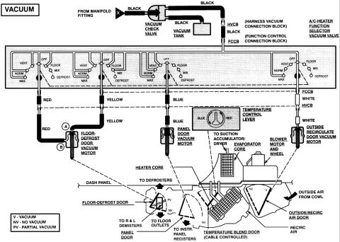





A/C-heater vacuum control diagram showing vacuum tank, check valve, function selector valve, and color-coded hoses to floor-defrost, recirculate and outside-air door vacuum motors.
Part of 1992-1996 Ford Bronco Vacuum Routing Diagrams
This document is a vacuum routing diagram for a Ford A/C-heater (HVAC) system, uploaded to the gallery of a 1995 Ford Bronco. It shows the vacuum supply path from the intake manifold fitting through a vacuum check valve to a vacuum tank, then via black hoses to the HVCB (Harness Vacuum Connection Block) and FCCB (Function Control Connection Block) feeding the A/C-heater function selector vacuum valve. The selector valve schematic shows internal porting for the OFF, VENT, FLOOR, NORM, MIX, MAX, and DEFROST positions. Color-coded vacuum lines run from the valve: red to the floor-defrost door vacuum motor (ports A and B), yellow also to that motor, blue to the panel door vacuum motor, and white (through FCCB/HVCB) to the outside/recirculate door vacuum motor. A pictorial view of the HVAC housing identifies the heater core, evaporator core, blower motor and wheel, suction accumulator/dryer connection, temperature control lever, temperature blend door (cable controlled), floor-defrost door, panel door, outside/recirc air door, and airflow paths to defrosters, demisters, floor outlets, and instrument panel registers. A legend defines V (vacuum), NV (no vacuum), and PV (partial vacuum) door position states.
Is this accurate? Sign in to help verify it.
Frequently asked questions
- What color vacuum line goes to the panel door vacuum motor?
- The blue vacuum line runs from the A/C-heater function selector vacuum valve to the panel door vacuum motor.
- Where does the HVAC system get its vacuum supply?
- Vacuum comes from a manifold fitting through a vacuum check valve to a vacuum tank, then via black hoses through the HVCB (harness vacuum connection block) and FCCB (function control connection block) to the function selector vacuum valve.
- What do V, NV, and PV mean on the diagram?
- Per the legend: V = Vacuum, NV = No Vacuum, PV = Partial Vacuum, indicating door positions under those vacuum states.
- Which vacuum lines control the floor-defrost door?
- The red and yellow lines from the selector valve go to the floor-defrost door vacuum motor, with red connecting at port A/B on the motor.
- How is the temperature blend door operated?
- The temperature blend door is cable controlled (not vacuum operated), driven by the temperature control lever.






No comments yet.