Home/
Registry/
Hyundai/
Genesis Coupe/
2010-2016/
“Coupe”/
Photo
supermotors.net/registry/media/1072202
Hyundai Genesis Coupe FATC Climate Control 97250-2MXXX Connector Pinout
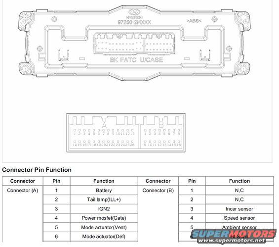
Schematic of a full-auto temperature control module showing connector A and B pin layouts and a function table for battery, IGN, and sensor pins.
Part of 2010-2016 Hyundai Genesis Coupe Schematics
This document is a schematic/reference page for a Hyundai full automatic temperature control (FATC) heater/climate control unit, showing the rear case of the control module labeled with Hyundai part number 97250-2MXXX and the markings '>ABS<' and 'BK FATC U/CASE'. Below the case drawing is a pinout diagram for the unit's two harness connectors: Connector A with 26 pins (numbered 1-13 on the top row and 14-26 on the bottom row) and Connector B with 16 pins (1-8 top, 9-16 bottom). A 'Connector Pin Function' table lists the first six pins of each connector: Connector A pin 1 Battery, pin 2 Tail lamp (ILL+), pin 3 IGN2, pin 4 Power mosfet (Gate), pin 5 Mode actuator (Vent), pin 6 Mode actuator (Def); Connector B pin 1 N,C, pin 2 N,C, pin 3 Incar sensor, pin 4 Speed sensor, pin 5 Ambient sensor, pin 6 HI-Scan. The table is cut off at the bottom of the scan, so remaining pins are not shown. This page is useful for diagnosing climate control inputs such as the in-car temperature sensor and ambient sensor on this FATC head unit.
Is this accurate? Sign in to help verify it.
Frequently asked questions
- What part number is on the Hyundai FATC climate control unit shown?
- The unit case is marked 97250-2MXXX, along with 'BK FATC U/CASE' and '>ABS<'.
- Which pin on the FATC connector carries the in-car (incar) temperature sensor signal?
- Connector B, pin 3 is the Incar sensor input.
- Where do the ambient and speed sensor inputs connect on the FATC unit?
- On Connector B: pin 4 is the Speed sensor and pin 5 is the Ambient sensor. Pin 6 is HI-Scan.
- What are the first pins of Connector A on this climate control head?
- Pin 1 Battery, pin 2 Tail lamp (ILL+), pin 3 IGN2, pin 4 Power mosfet (Gate), pin 5 Mode actuator (Vent), pin 6 Mode actuator (Def).
- How many pins do the FATC unit connectors have?
- Connector A has 26 pins (1-13 top row, 14-26 bottom row) and Connector B has 16 pins (1-8 top row, 9-16 bottom row).
Comments
More from this build









No comments yet.